LAARS Heating Systems
Page 110
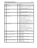
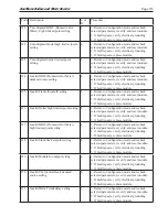
Code Description
L or
H
Procedure
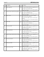
153
Combustion Pressure Off
H or
L
1. Check wiring and correct any errors.
2. Inspect the Combustion Pressure Switch to
make sure it is working correctly.
3. Reset and sequence the relay module.
4. During STANDBY and PREPURGE, measure
the voltage between J6 terminal 5 and L2 (N).
Supply voltage should be present. If not, the
lockout switch is defective and needs replacing.
5. If the fault persists, replace the relay module.
154
Purge Fan switch On
H or
L
1. Purge fan switch is on when it should be off.
2. Check wiring and correct any errors.
3. Inspect the Purge Fan switch J6 terminal 3 and
its connections. Make sure the switch is working
correctly and is not jumpered or welded.
4. Reset and sequence the relay module.
5. If the fault persists, replace the relay module.
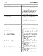
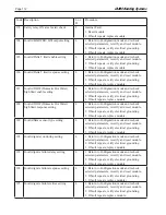
155
Purge fan switch OFF
H or
L
1. Purge fan switch is off when it should be on.
2. Check wiring and correct any errors.
3. Inspect the Purge Fan switch J6 terminal 3 and
its connections. Make sure the switch is working
correctly and is not jumpered or welded.
4. Reset and sequence the relay module.
5. If the fault persists, replace the relay module.
156
Combustion pressure and flame ON
H or
L
1. Check that flame is not present in the
combustion chamber. Correct any errors.
2. Make sure that the flame detector is wired to
the correct terminal.
3. Make sure the F & G wires are protected from
stray noise pickup.
4. Reset and sequence the module, if code
reappears, replace the flame detector.
5. Reset and sequence the module, if code
reappears, replace the module.
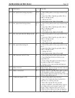
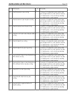
157
Combustion pressure and flame OFF
L
1. Check that flame is not present in the
combustion chamber. Correct any errors.
2. Make sure that the flame detector is wired to
the correct terminal.
3. Make sure the F & G wires are protected from
stray noise pickup.
4. Reset and sequence the module, if code
reappears, replace the flame detector.
5. Reset and sequence the module, if code
reappears, replace the module.
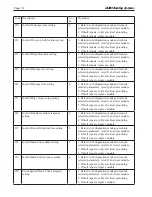
158
Main valve ON
L
1. Check Main Valve terminal wiring and correct
any errors.
2. Reset and sequence the module. If fault
persists, replace the module.
Summary of Contents for NTV1000
Page 2: ......
Page 35: ...NeoTherm Boilers and Water Heaters Page 31 Fig 20 Ladder Diagram...
Page 36: ...LAARS Heating Systems Page 32 Fig 21 Wiring Diagram...
Page 37: ...NeoTherm Boilers and Water Heaters Page 33...
Page 51: ...NeoTherm Boilers and Water Heaters Page 47 Fig 52 Connection Terminals...
Page 130: ...LAARS Heating Systems Page 126 Fig 140 Machine Frame and Rear Panel 13 3 PARTS ILLUSTRATIONS...
Page 131: ...NeoTherm Boilers and Water Heaters Page 127 Fig 141 Front Panel and Covers...
Page 132: ...LAARS Heating Systems Page 128 Fig 142 Burners and Combustion Chambers...
Page 134: ...LAARS Heating Systems Page 130 Fig 145 Electronic Components...
Page 135: ...NeoTherm Boilers and Water Heaters Page 131 Fig 146 Condensate Trap Fig 147 Control Bezel...
Page 136: ...LAARS Heating Systems Page 132 Fig 148 Flow Switch...
Page 137: ...NeoTherm Boilers and Water Heaters Page 133 This page intentionally left blank...


