NeoTherm Boilers and Water Heaters
Page 119
12.7 analysis
The control system includes an Analysis branch
that can display the behavior over a period of time
for several different parameters: fan speed, outlet
temperature, inlet temperature, etc.
How to get there –
Home Page <Select icon> Status Summary Screen
<Details button> Any Configuration Screen <Analysis
button> Trend Analysis Screen
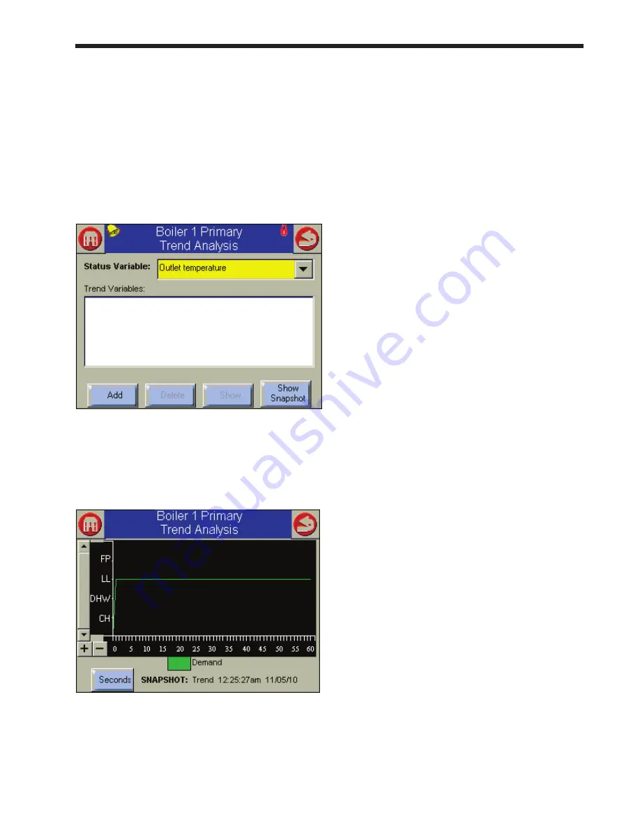
fig. 138 – analysis Setup Screen
To use this function, select the parameter you want
to track from the pull-down list. The system will
present a graph that tracks that variable.
fig. 139 – trend analysis Graph
The time scale can be adjusted by pressing the
Seconds button in the lower left-hand corner.
12.8 operating Sequence
Initiation
Each controller enters the Initiation sequence after
one of these conditions:
•
Initial power up
•
Voltage fluctuations vary +10% or -15%
•
Frequency fluctuations vary ±10%
•
The demand, limit control input, or TT signals
are interrupted during the prepurge period.
•
After the Reset button is pressed.
•
After a Fault is cleared using the displays.
The Initiation sequence also delays the boiler
demand from being energized and re-energized from
an intermittent AC line input or control input. If
an AC problem exists for more than 240 seconds, a
lockout will occur.
Start-Up Checks in a lead/lag System
For an explanation of Lead/Lag operation, see the
first part of Section 9. In this section, we will focus
on the aspects of Lead/Lag that might be helpful in
troubleshooting.
When a Lead/Lag system is first powered up, the
controller acting as the Lead/Lag Master goes
through a “synchronization” process. During
synchronization, the controller establishes
communications with each of the Slave controllers
via the Modbus link. The Slave controllers
download some setup parameters and operating
history information. (On a system with several
boilers, this phase can take several minutes.) If the
Master cannot establish communications with one of
the Slaves, it triggers a Hold or Lockout.
The Master also checks the status of each of the flap
valves. If the Master cannot determine whether a
flap valve is open or closed, or if it cannot locate the
correct number of flap valves, it triggers a lockout or
hold.
If the system passes the checks described above,
each of the individual controller and burner
combinations is free to operate in the normal
way. The self-check and firing sequence for each
individual controller and burner combination is
described in the following section.
Summary of Contents for NTV1000
Page 2: ......
Page 35: ...NeoTherm Boilers and Water Heaters Page 31 Fig 20 Ladder Diagram...
Page 36: ...LAARS Heating Systems Page 32 Fig 21 Wiring Diagram...
Page 37: ...NeoTherm Boilers and Water Heaters Page 33...
Page 51: ...NeoTherm Boilers and Water Heaters Page 47 Fig 52 Connection Terminals...
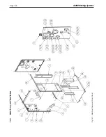
Page 130: ...LAARS Heating Systems Page 126 Fig 140 Machine Frame and Rear Panel 13 3 PARTS ILLUSTRATIONS...
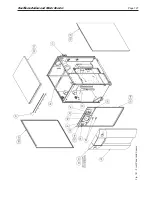
Page 131: ...NeoTherm Boilers and Water Heaters Page 127 Fig 141 Front Panel and Covers...
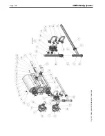
Page 132: ...LAARS Heating Systems Page 128 Fig 142 Burners and Combustion Chambers...
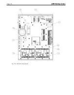
Page 134: ...LAARS Heating Systems Page 130 Fig 145 Electronic Components...
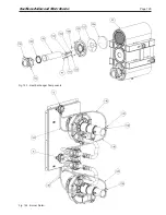
Page 135: ...NeoTherm Boilers and Water Heaters Page 131 Fig 146 Condensate Trap Fig 147 Control Bezel...
Page 136: ...LAARS Heating Systems Page 132 Fig 148 Flow Switch...
Page 137: ...NeoTherm Boilers and Water Heaters Page 133 This page intentionally left blank...

