LAARS Heating Systems
Page 24
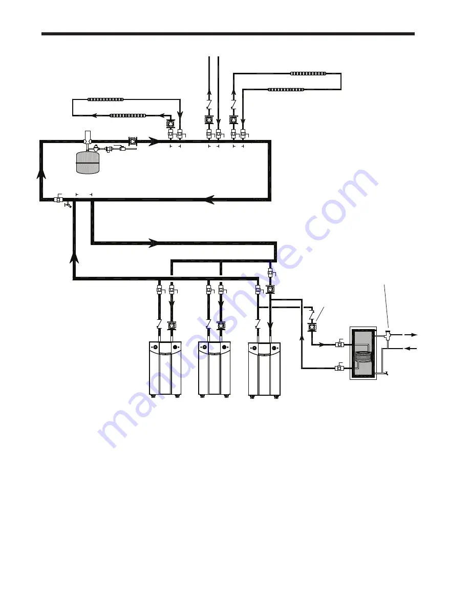
fig. 15 - Hydronic Piping — multiple Boilers, Indirect DHW off of one Boiler
Space heating zone circuits
Space heating zone circuit
Air vent
Water feed
controls
Expansion tank
Common piping must be sized for the
combined water flow of all the boilers.
High temp. space heating zone circuit
4 pipe dia. max.
4 pipe dia. max. 4 pipe dia. max.
Indirect
DWH tank
Note -
Indirect pump
must be sized
for boiler and
indirect
Anti-scald
mixing valve
Domestic
hot water
out
Cold
water
Note -
In this piping arrangement,
the boiler pump must turn off
during DHW operation.
Note -
This drawing is a schematic
representation of a piping style,
and is not intended to be used
as a working installation drawing.
Local code requirements
must be met.
Summary of Contents for NTV1000
Page 2: ......
Page 35: ...NeoTherm Boilers and Water Heaters Page 31 Fig 20 Ladder Diagram...
Page 36: ...LAARS Heating Systems Page 32 Fig 21 Wiring Diagram...
Page 37: ...NeoTherm Boilers and Water Heaters Page 33...
Page 51: ...NeoTherm Boilers and Water Heaters Page 47 Fig 52 Connection Terminals...
Page 130: ...LAARS Heating Systems Page 126 Fig 140 Machine Frame and Rear Panel 13 3 PARTS ILLUSTRATIONS...
Page 131: ...NeoTherm Boilers and Water Heaters Page 127 Fig 141 Front Panel and Covers...
Page 132: ...LAARS Heating Systems Page 128 Fig 142 Burners and Combustion Chambers...
Page 134: ...LAARS Heating Systems Page 130 Fig 145 Electronic Components...
Page 135: ...NeoTherm Boilers and Water Heaters Page 131 Fig 146 Condensate Trap Fig 147 Control Bezel...
Page 136: ...LAARS Heating Systems Page 132 Fig 148 Flow Switch...
Page 137: ...NeoTherm Boilers and Water Heaters Page 133 This page intentionally left blank...


