LAARS Heating Systems
Page 34
Section 8
USInG tHe ControlS on tHe
neotHerm 1000
8.1
Controls and Indicators on the
front of the Unit
There are only a few controls and indicators on the
front of the unit. See Fig. 22. Most of the control
functions are done using the Operator Interface
panel.
8.2 Using the operator Interface
The NeoTherm 1000 uses a color touch screen
Operator Interface to get input from the operator
or installer, and to present information about the
operation of the boiler. Each boiler includes a
touchscreen, but in a typical installation, only the
touchscreen on one of the boilers will be active.
fig. 22 - Controls and Indicators on front of Unit
On/Off
switch
Operator
interface
panel
Boiler
outlet
temperature
and system
pressure
fig. 23 - operator Interface
Most of the control functions are done using the
touch screen area in the center of the panel.
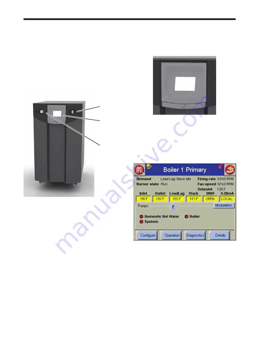
Here’s a typical screen or “page” presented by the
system:
fig. 24 - Status Summary Screen
Summary of Contents for NTV1000
Page 2: ......
Page 35: ...NeoTherm Boilers and Water Heaters Page 31 Fig 20 Ladder Diagram...
Page 36: ...LAARS Heating Systems Page 32 Fig 21 Wiring Diagram...
Page 37: ...NeoTherm Boilers and Water Heaters Page 33...
Page 51: ...NeoTherm Boilers and Water Heaters Page 47 Fig 52 Connection Terminals...
Page 130: ...LAARS Heating Systems Page 126 Fig 140 Machine Frame and Rear Panel 13 3 PARTS ILLUSTRATIONS...
Page 131: ...NeoTherm Boilers and Water Heaters Page 127 Fig 141 Front Panel and Covers...
Page 132: ...LAARS Heating Systems Page 128 Fig 142 Burners and Combustion Chambers...
Page 134: ...LAARS Heating Systems Page 130 Fig 145 Electronic Components...
Page 135: ...NeoTherm Boilers and Water Heaters Page 131 Fig 146 Condensate Trap Fig 147 Control Bezel...
Page 136: ...LAARS Heating Systems Page 132 Fig 148 Flow Switch...
Page 137: ...NeoTherm Boilers and Water Heaters Page 133 This page intentionally left blank...


