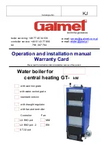
NeoTherm Boilers and Water Heaters
Page 41
8.8
Verification Process for Safety-
related Parameters
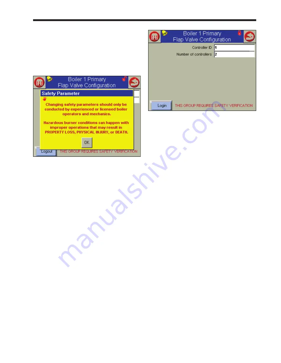
1. When you start to change a parameter that
is related to safety, the system will present a
warning which looks like this:
fig. 41 - Parameter Safety Warning
Press OK to continue. The system will ask
you to login before you make a change. (For
more information on logging in, see Section
8.2.)
Note that any changes you make will apply
only to one controller – the controller you
have already selected. If you want the same
change to apply to other controllers, you must
change each of them separately.
2. If you make a change in any group that could
affect the safe operation of the unit, the control
system will ask you to “verify” the change
before it is accepted. As an example, let’s say
that we wanted to change the configuration
for one of the flap valves. See Fig. 42. A
line printed in red at the bottom of the screen
indicates that the system wants to do a safety
verification. (All of the parameters in this
group have safety-related functions. If you
change any of them, you will have to do the
verification for the whole group.)
Fig. 42 - Verification Needed
notes –
• Once you change one of these safety-related
parameters, you
must
finish the verification
process for the group that includes the parameter,
or the control system will not let the boiler
operate
. You can wait to do the verification until
you have changed parameters in other groups,
but before you return the boiler to service, you
have to do the verification for all of the groups you
changed.
• At the end of the verification process, you
must press the Reset button on the front of the
controller. See Fig. 43. You have to do this within
30 seconds, or the verification will be cancelled.
To make it easy to reach the Reset button, open
the door on the front of the boiler and slide out the
control panel
before
beginning the verification.
Summary of Contents for NTV1000
Page 2: ......
Page 35: ...NeoTherm Boilers and Water Heaters Page 31 Fig 20 Ladder Diagram...
Page 36: ...LAARS Heating Systems Page 32 Fig 21 Wiring Diagram...
Page 37: ...NeoTherm Boilers and Water Heaters Page 33...
Page 51: ...NeoTherm Boilers and Water Heaters Page 47 Fig 52 Connection Terminals...
Page 130: ...LAARS Heating Systems Page 126 Fig 140 Machine Frame and Rear Panel 13 3 PARTS ILLUSTRATIONS...
Page 131: ...NeoTherm Boilers and Water Heaters Page 127 Fig 141 Front Panel and Covers...
Page 132: ...LAARS Heating Systems Page 128 Fig 142 Burners and Combustion Chambers...
Page 134: ...LAARS Heating Systems Page 130 Fig 145 Electronic Components...
Page 135: ...NeoTherm Boilers and Water Heaters Page 131 Fig 146 Condensate Trap Fig 147 Control Bezel...
Page 136: ...LAARS Heating Systems Page 132 Fig 148 Flow Switch...
Page 137: ...NeoTherm Boilers and Water Heaters Page 133 This page intentionally left blank...


