NeoTherm Boilers and Water Heaters
Page 61
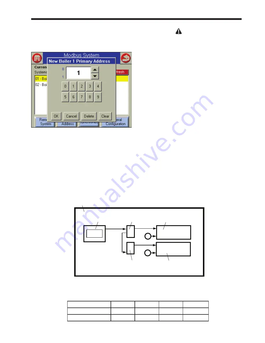
8. Press the Change Address button again. The
system will present a screen that lets you
change the address.
fig. 68 – Changing modbus address
9. Table 13 shows how the Modbus control
addressing should be set up. The system is
simple, but it is important to only use the
correct address listed in the table. Do not use
any other address than the one listed in the
table for the control you are addressing. In this
example, the correct address for the Primary
Control on Boiler 1 is “1.” If this is not already
set to “1”, enter the correct number, then press
OK.
Boiler 1
Boiler 2
Boiler 3
Boiler 4
Primary control
1
3
5
7
Secondary control
2
4
6
8
table 13 – modbus Control addressing
WarnInG
If the addresses are not assigned properly, the
system could fail to operate correctly, or it might
operate in an unsafe manner. This could lead to
property damage, personal injury or death.
10. Now you can use the same process to set the
address for the Secondary control for Boiler 1.
On the Modbus System Configuration screen
(Fig. 67), press the second line – Boiler 1
Secondary. Change the address to the correct
address taken from Table 3. In this case, the
correct address would be “2.”
11. Go to the Operator Interface for Boiler 2.
Repeat the process to change the addresses for
Boiler 2 Primary (address = 3) and Boiler 2
Secondary (address = 4).
12. Repeat steps 3 - 10 for each of the other
controllers connected to the system.
Job f - Set the flap Valve IDs
(These are individual functions. Make the flap valve assignment
on each of the controllers. Use the Operator Interface on each of
the boilers.)
Do this on any system with multiple boilers.
Each boiler includes two burners, and each burner
has a flap valve. See Fig. 69.
Primary
burner
Primary
controller
Flap
valve
Flap
valve
Secondary
controller
Secondary
burner
Operator
interface
Boiler 1
fig. 69 - flap Valve arrangement
Summary of Contents for NTV1000
Page 2: ......
Page 35: ...NeoTherm Boilers and Water Heaters Page 31 Fig 20 Ladder Diagram...
Page 36: ...LAARS Heating Systems Page 32 Fig 21 Wiring Diagram...
Page 37: ...NeoTherm Boilers and Water Heaters Page 33...
Page 51: ...NeoTherm Boilers and Water Heaters Page 47 Fig 52 Connection Terminals...
Page 130: ...LAARS Heating Systems Page 126 Fig 140 Machine Frame and Rear Panel 13 3 PARTS ILLUSTRATIONS...
Page 131: ...NeoTherm Boilers and Water Heaters Page 127 Fig 141 Front Panel and Covers...
Page 132: ...LAARS Heating Systems Page 128 Fig 142 Burners and Combustion Chambers...
Page 134: ...LAARS Heating Systems Page 130 Fig 145 Electronic Components...
Page 135: ...NeoTherm Boilers and Water Heaters Page 131 Fig 146 Condensate Trap Fig 147 Control Bezel...
Page 136: ...LAARS Heating Systems Page 132 Fig 148 Flow Switch...
Page 137: ...NeoTherm Boilers and Water Heaters Page 133 This page intentionally left blank...


