LAARS Heating Systems
Page 62
A flap valve acts like a one-way valve or check valve.
If one burner in a boiler is operating, and the other
is not, one of the flap valves will close to prevent
exhaust air from moving backwards through the
burner that is not operating.
Before the Lead/Lag Master controller will allow
the system to operate, it must be able to determine
whether each of these flap valves is open or closed.
If the controller cannot find a signal from one of the
flap valves, the control system will act to prevent
backflow by energizing the blower of the control
with the bad flap valve. (The positive pressure from
the blower will prevent the exhaust air from moving
back through the burner.) If this cannot be done, the
Lead/Lag Master controller will not allow the whole
system to run. For this reason, it is important that all
of the flap valves be identified correctly.
Each controller in the system needs to know how
many controllers are included in the whole system.
You will need to enter this information in each of the
controllers separately.
WarnInG
If the flap valve identifications are not configured
correctly, this could cause the equipment to
malfunction. This could lead to personal injury or
death, and could damage the equipment. If the
configuration is not correct, the control system will
present an error – “HOLD 119 – Control Interaction
Fault” on the display, and will prevent the boiler(s)
from operating.
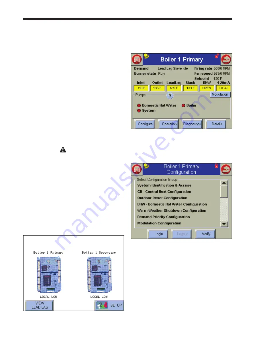
1. Let’s start by setting the Flap Valve ID for the
Primary control for Boiler 1. To do this, start
at the Home screen (Fig. 70). (To reach the
Home screen, press the Home icon in the upper
left corner of any screen.)
fig. 70 – Home Screen
2. Press the icon for the controller you want to
work with. The system will take you to the
Status Summary screen for that controller.
fig. 71 – Status Summary Screen
3. Press the Configure button. Figure 72 shows
the Configuration screen.
Fig. 72 – Configuration Screen
4. Scroll through the listing on the Configure
menu to Flap Valve Configuration, and select
that line. See Fig. 73.
Summary of Contents for NTV1000
Page 2: ......
Page 35: ...NeoTherm Boilers and Water Heaters Page 31 Fig 20 Ladder Diagram...
Page 36: ...LAARS Heating Systems Page 32 Fig 21 Wiring Diagram...
Page 37: ...NeoTherm Boilers and Water Heaters Page 33...
Page 51: ...NeoTherm Boilers and Water Heaters Page 47 Fig 52 Connection Terminals...
Page 130: ...LAARS Heating Systems Page 126 Fig 140 Machine Frame and Rear Panel 13 3 PARTS ILLUSTRATIONS...
Page 131: ...NeoTherm Boilers and Water Heaters Page 127 Fig 141 Front Panel and Covers...
Page 132: ...LAARS Heating Systems Page 128 Fig 142 Burners and Combustion Chambers...
Page 134: ...LAARS Heating Systems Page 130 Fig 145 Electronic Components...
Page 135: ...NeoTherm Boilers and Water Heaters Page 131 Fig 146 Condensate Trap Fig 147 Control Bezel...
Page 136: ...LAARS Heating Systems Page 132 Fig 148 Flow Switch...
Page 137: ...NeoTherm Boilers and Water Heaters Page 133 This page intentionally left blank...


