LAARS Heating Systems
Page 68
Here are the settings on this screen:
Master enable -
Enabled = Lead/Lag system enabled
CH setpoint -
Setpoint for LL Central Heating
CH time of day setpoint -
Separate Time-of-Day Setpoint for Central
Heating (See the material on “About the
‘Time of Day’ Function at the end of this
section)
DHW setpoint -
Setpoint for Domestic Hot Water
DHW time of day setpoint -
Separate Time-of-Day Setpoint for Domestic
Hot Water (See the material on “About the
‘Time of Day’ Function at the end of this
section)
Modbus port -
Always use MB1
6. To see the other settings related to the Lead/
Lag functions, press the button for Advanced
Settings. This leads to a “ring” of related
screens, and you can scroll through the list by
pressing one of the left- or right-arrow symbols.
The screens in this ring are:
Modulation
Central Heat
Domestic Hot Water
Outdoor Reset
Warm Weather Shutdown
Algorithms
Rate Allocation
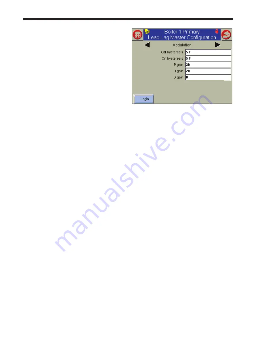
7. Press the left-arrow or right-arrow until you see
the Modulation screen (Fig. 86).
fig. 86 – modulation
Off hysteresis -
The system will not shut off the burners until
the System sensor reaches the CH Setpoint
plus an additional “hysteresis” value.
On hysteresis -
The system will not fire the burners until the
System sensor reaches the LL CH Setpoint
minus an additional “hysteresis” value.
P, I, D Gain -
These control the “damping” used by the
temperature control. The three control
values are P (proportional), I (integral) and
D (derivative). If you understand how these
variables affect the function of the unit,
you can change them to adjust for unusual
operating conditions. The default settings
for the Lead/Lag configuration are: P = 30, I
= 20, and D = 0.
Summary of Contents for NTV1000
Page 2: ......
Page 35: ...NeoTherm Boilers and Water Heaters Page 31 Fig 20 Ladder Diagram...
Page 36: ...LAARS Heating Systems Page 32 Fig 21 Wiring Diagram...
Page 37: ...NeoTherm Boilers and Water Heaters Page 33...
Page 51: ...NeoTherm Boilers and Water Heaters Page 47 Fig 52 Connection Terminals...
Page 130: ...LAARS Heating Systems Page 126 Fig 140 Machine Frame and Rear Panel 13 3 PARTS ILLUSTRATIONS...
Page 131: ...NeoTherm Boilers and Water Heaters Page 127 Fig 141 Front Panel and Covers...
Page 132: ...LAARS Heating Systems Page 128 Fig 142 Burners and Combustion Chambers...
Page 134: ...LAARS Heating Systems Page 130 Fig 145 Electronic Components...
Page 135: ...NeoTherm Boilers and Water Heaters Page 131 Fig 146 Condensate Trap Fig 147 Control Bezel...
Page 136: ...LAARS Heating Systems Page 132 Fig 148 Flow Switch...
Page 137: ...NeoTherm Boilers and Water Heaters Page 133 This page intentionally left blank...


