LAARS Heating Systems
Page 72
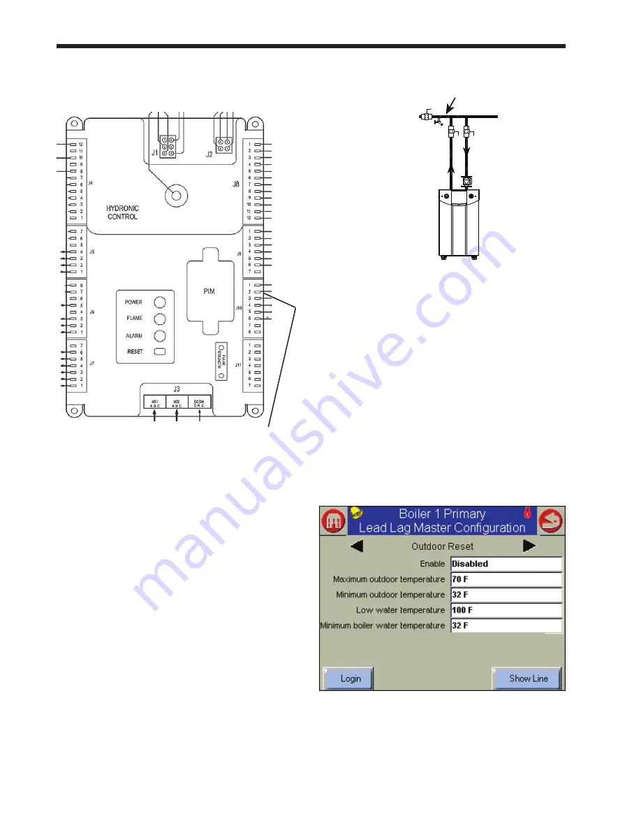
The input for the Time of Day function must be wired
to pins 2 and 3 on connector J10.
fig. 93 – Connections for “time of Day” function
Job J - Install System Sensor and adjust
Setpoint
(This is a Lead/Lag function – do this once for the whole Lead/
Lag system. Make the connections to the controller set up as the
Lead/Lag Master – usually the Primary controller on Boiler 1.)
1. Install the System sensor at the location shown
in Fig. 94. Connect the System sensor to the
System terminals on the controller acting as
the Lead/Lag Master (usually the Primary
controller on Boiler 1.) Use terminals 3 and 4
on TB6.
2. Adjust the Lead/Lag Central Heat Setpoint
to the desired temperature to be used by the
system.
How to get there – Adjust CH Setpoint
Home Page <Press View Lead Lag button> Lead Lag
Screen <Press Lead Lag Master button> Lead Lag Screen
<Press Configure button> Lead Lag Master Configuration
Screen
Line 2 = CH Setpoint
fig. 94 – mounting location for System Sensor
Job K - Set lead lag outdoor reset and
Warm Weather Shutdown
(This is a Lead/Lag function – do this once for the whole Lead/
Lag system. Use the controller set up as the Lead/Lag Master –
usually the Primary controller on Boiler 1.)
For more information on the outdoor reset function,
see the explanation which follows.
1. Install the outdoor air temperature sensor and
make the connections to the outdoor air sensor
terminals on the controller acting as the Lead/
Lag Master (usually the Primary controller on
Boiler 1.) Use terminals 1 and 2 on TB7.
2. Set the outdoor reset and warm weather
shutdown parameters as desired.
How to get there – Outdoor Reset Screen and Warm
Weather Shutdown Screen
Home Page <Press View Lead/ Lag button> Lead/ Lag
Screen <Press Lead/ Lag Master button> Lead/ Lag
Screen <Press Configure button> Lead/ Lag Master
Configuration Screen <Press Advanced Settings button>
Select the Outdoor Reset Screen or the Warm Weather
Shutdown Screen
fig. 95 – outdoor reset
For a detailed explanation of the Outdoor Reset
function, see the section titled “About Outdoor
Reset” which follows.
Pins 2 and 3 on
connector J10
Summary of Contents for NTV1000
Page 2: ......
Page 35: ...NeoTherm Boilers and Water Heaters Page 31 Fig 20 Ladder Diagram...
Page 36: ...LAARS Heating Systems Page 32 Fig 21 Wiring Diagram...
Page 37: ...NeoTherm Boilers and Water Heaters Page 33...
Page 51: ...NeoTherm Boilers and Water Heaters Page 47 Fig 52 Connection Terminals...
Page 130: ...LAARS Heating Systems Page 126 Fig 140 Machine Frame and Rear Panel 13 3 PARTS ILLUSTRATIONS...
Page 131: ...NeoTherm Boilers and Water Heaters Page 127 Fig 141 Front Panel and Covers...
Page 132: ...LAARS Heating Systems Page 128 Fig 142 Burners and Combustion Chambers...
Page 134: ...LAARS Heating Systems Page 130 Fig 145 Electronic Components...
Page 135: ...NeoTherm Boilers and Water Heaters Page 131 Fig 146 Condensate Trap Fig 147 Control Bezel...
Page 136: ...LAARS Heating Systems Page 132 Fig 148 Flow Switch...
Page 137: ...NeoTherm Boilers and Water Heaters Page 133 This page intentionally left blank...


