background image

Page 

6

 of 

10


 Lab12 suara 2 x 50W 

Class A Power Amplifier


Front Panel  


Suara Front panel


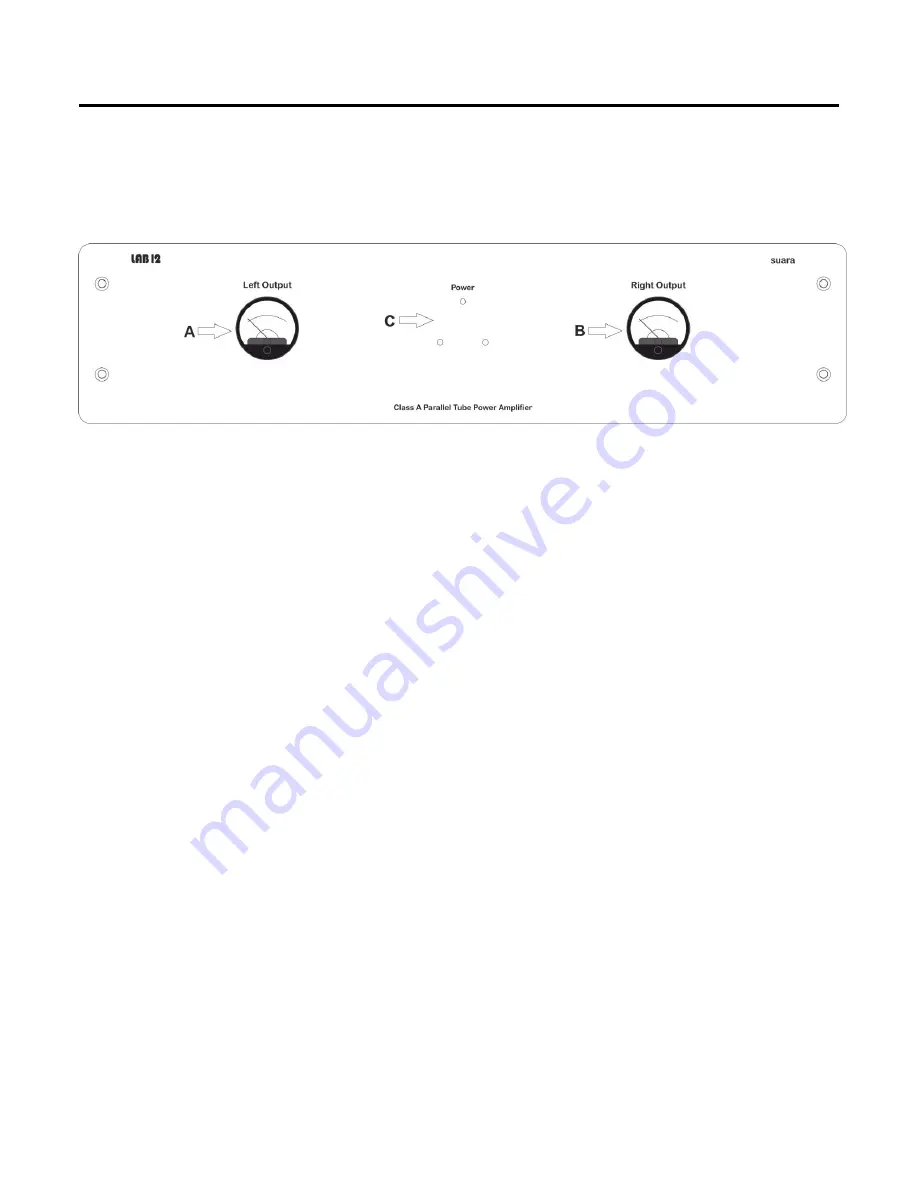
At front panel you will see three indication LEDs and two VU meters. 

The three LEDs  (

C

) indicate that the device is powered on.  

To the left of 3 LEDs you see a retro analog VU meter (

A

). You can accurately monitor the output level 

of left channel on dB scale. 

To the right of 3 LEDs you see a retro analog VU meter (

B

). You can accurately monitor the output level 

of right channel on dB scale. 


Summary of Contents for Suara

Page 1: ...Page 1 of 10 Owner s Manual suara Parallel tubes 2 x 50W Class A Power Amplifier www lab12 gr manual v1 0...

Page 2: ...Table of Contents It is yours page 3 Features page 4 Installation Placement page 4 Suara Tubes Position page 5 Front Panel page 6 Rear Panel page 7 Main connections page 8 Bias Setting page 9 For the...

Page 3: ...carefully chosen after hours of listening and testing while paying great attention to every detail affecting the final outcome As every Lab12 device suara has an ultra solid construction with handcra...

Page 4: ...allation Placement The Lab12 suara should be placed on a solid flat surface You should avoid placing it near a heat source as this could compromise the suara s performance and reliability Carefully pu...

Page 5: ...sitions Insert the tubes carefully in each position All of the tubes are marked with the position number was placed during calibration and factory burn in of suara All in box tubes are perfectly match...

Page 6: ...Ds and two VU meters The three LEDs C indicate that the device is powered on To the left of 3 LEDs you see a retro analog VU meter A You can accurately monitor the output level of left channel on dB s...

Page 7: ...IEC AC input including a main fuse holder C A pair of RCA and XLR connectors for each channel B are the inputs of signal from your preamplifier Speaker outputs for each channel A giving you the choic...

Page 8: ...kers from 2 to 4 ohm at 4ohm positive bind speakers from 6 to 16 ohm at 8ohm bind Make sure about the phase and polarity of speakers always connect plus red bind of suara to plus red bind of speaker a...

Page 9: ...to bias Use trimming screwdriver to set the voltage at 950mV DC KT150 setting from corresponding trimmer Follow the same procedure for each tube Wrong bias will destroy your tubes and possibly your am...

Page 10: ...20 Hz 25 KHz 0 9dB Input impedance 100 K ohms Recommended speakers 4 8 ohm Tube complement 2x 6n1p dual triode 2x 6n2p 4 x KT 150 Power Pentode Input sensitivity 750mV Inputs 1x line unbalanced stereo...

Reviews: