background image

16  

C Series Operation Manual 

7.4  Audio Input and Output con-

nections, setup and features

7.4.1  Balanced / unbalanced Input connection

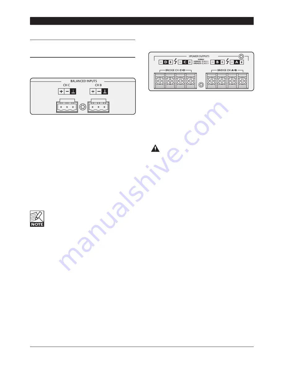
Two electronically balanced Phoenix-type inputs are 
available. Follow the +,– and Ground labels when 
connecting the input signal. 

If an unbalanced connection is desired this can be 
achieved  by  summing  the  minus  (“COLD”)  and 
Ground terminals and using the + terminal as the 
“HOT” signal. For the best possible performance, 
the summing of ground and minus wires should be 
done at the source unit end of the cable (e.g. a CD 
player).

Four connectors are supplied for attaching cables to 
the inputs. The type of connector used is: Phoenix 
Contacts, Part number MSTB 2,5/3-STZ-5,08

When linking the same source signal to 

several input channels, be aware that there 
is  a  limit  to  the  number  of  channels  an 
output source can “drive”. A typical output 

source (e.g. a DSP crossover unit) can drive up to 4 
amplifier  channels  before  line-drivers  would  be  
required to buffer the signal.

7.4.  Output operation and connection

Screw-terminal connectors with + and – poles are 
provided at each channel output for connection of 
the speakers. 

Make sure that the speaker cables are connected 
correctly and tightly, and that accurate polarity is 
maintained to all speakers in the system.

As the amplifier outputs produce high voltage, 

do not connect or disconnect speaker cables 

when the mains power is on. Also, attach the safety 
cover on the speaker terminals for safe operation 
and to comply with electrical product approvals. 

7.4.3  Output bridge mode

It is possible to bridge channels in pairs of two (A+B 
and  C+D  for  example).  When  bridged,  the  input 
source must be connected to input A (A+B) or C 
(C+D) respectively. Output speaker cables must be 
connected to the plus pole on channel A or C and 
the minus pole on B or D.


The main benefit of bridging the output is a doubling 
of output voltage. Bridging can be used to turn the 
amplifier into a 3 channel amplifier with, for example, 
2x1200 W and 1x2400 W at 4 ohms utilizing the C 
48:4, or simply to achieve an impressive 200 Vrms 
supply per channel.

Most  power  amplifier  designs,  when  bridged,  
automatically introduce a +6 dB input gain boost 
which  can  lead  the  user  to  conclude  that  said  
amplifier delivers “more than double the power” 
when in bridge mode. This is clearly not the case, as 
the gain boost artificially enhances perceived power 
at the costof headroom. The C Series amplifiers 
work on globally set constant gain, and automatically 
compensate the input gain by -6 dB. For example, if 
the amplifier is configured in a three channel mode, 
then the selected gain is maintained from input to 
output on all channels.

7  OPERATION AND PERFORMANCE

Summary of Contents for C 68:4

Page 1: ...Rev 2 01 Operation manual C Series Installation Dedicated Amplifiers C 68 4 C 48 4 C 28 4 C 16 4 Part no UM CS...

Page 2: ...and performance optimization 7 4 2 5 NomadLink Ethernet control and monitoring network 7 5 installation 8 5 1 Unpacking 8 5 2 Mounting 8 5 3 Cooling 8 5 4 Operating voltage 8 5 5 Grounding 9 6 quick g...

Page 3: ...ng open load 19 7 5 6 Lo impedance protection short circuit 19 7 5 7 Temperature protection 20 7 5 8 Power Average Limiter PAL 20 7 5 9 Soft Start 20 7 6 Front panel monitoring and adjustments 21 7 6...

Page 4: ...r replacement of the obsolete outlet Connect only to AC power outlets rated 100 120 V or 200 240 V 50 60 Hz Do not use this amplifier if the power cord is broken or frayed Protect the power cord from...

Page 5: ...pment on and off the user is encouraged to try to correct the interference by one or more of the following measures Reorient or relocate the antenna Increase the separation between the equipment and r...

Page 6: ...impedance or constant voltage 70 V 100 V mode NomadLink an easy to use network for monitoring and control is implemented as a standard feature on all C Series amplifiers Although C Series features and...

Page 7: ...d a malfunctioning cable or driver is short circuiting the output High impedance warning reports an alert when at the same time output signal is high simultane ously and no current draw is measured Th...

Page 8: ...sufficient space to allow the exhaust to escape If the amplifier is rack mounted do not use covers or doors on the front or rear of the rack Should a heat sink overheat the temperature sensing circuit...

Page 9: ...h power is controlled and limited during soft start enabling multiple amplifiers to be powered up simultaneously 5 5 Grounding There is no ground lift switch or terminal on the C Series amplifiers The...

Page 10: ...will not switch on until a Power On command is received from the network When the remote switch is off it is not possible to switch amplifier power on or off using NomadLink network control 6 1 2 Fron...

Page 11: ...t fan feature lowers fan speed when no signal is present Bridged A B and C D Switches the channel pairs into bridged mode operation automatic 6 dB gain compensation VPL Voltage Peak Limiter adjustment...

Page 12: ...erCon XLR type housings on the cables US National Differences cl 16 3 requires that NomadLink network cables must be rated VW 1 The OUT port from the NLB 60E must be connected to the IN port of the fi...

Page 13: ...C Series Operation Manual 13...

Page 14: ...Amplifier Overall amplifier input gain is adjusted using the input stage DIP switches Please note that the gain setting is global affecting all four channels Following the input stage the dedicated l...

Page 15: ...right Complete input sensitivity tables for all VPL and Gain settings for all C Series models can be found at www labgruppen com The headroom available through the input stage to the clip limiter is...

Page 16: ...ained to all speakers in the system As the amplifier outputs produce high voltage do not connect or disconnect speaker cables when the mains power is on Also attach the safety cover on the speaker ter...

Page 17: ...2 Amplifier sensitivity Sensitivity is defined as how many Volts rms or dBu referred to 0 775 Vrms are required to achieve full maximum output power As the output power varies with the load impedance...

Page 18: ...matically un mute An input signal must be present to allow detection of short circuit or low impedance conditions If the CPL LED is steadily illuminated orange while the output is muted and the 4 dB s...

Page 19: ...er Output will be muted long before maximum output power is attained To measure the true peak output power use a burst signal 7 5 4 DC protection DC protection is implemented on each output to prevent...

Page 20: ...ntervals The output will un mute when the channel or power supply returns to a safe operating temperature 7 5 8 Power Average Limiter PAL The Power Average Limiter PAL controls the current drawing rel...

Page 21: ...no speaker is connected For more detailed signal level indications use the DeviceControl editor application 1 2 3 4 5 8 6 2 Level adjust Step Attenuation 1 Min Inf dB 2 Inf dB 3 50 dB 4 40 dB 5 35 dB...

Page 22: ...ce When detected the output will mute for 6 seconds before re measuring the output impedance This will continue until the short circuit is removed CPL remains constant orange in a fault condition only...

Page 23: ...B 60E Should an amplifier fail or be inadvertently disconnected from the mains OPERATION AND PERFORMANCE 7 network integrity is fully maintained and all amplifiers remain visible on the system 7 7 2 C...

Page 24: ...between amplifiers Ethernet Cat5 Ethernet Cat5 Ethernet Cat5 Ethernet Cat5 NLB 60E IN OUT 300m 980ft 300m 980ft 100m 328ft total cable length for links in between amplifiers 300m 980ft Amp 1 IN OUT Am...

Page 25: ...Control editor The DeviceControl editor is Lab gruppen s proprietary software application for monitoring and controlling networked C Series power amplifiers DeviceControl runs on a Windows PC which co...

Page 26: ...feet In a non closed loop daisy chained subnet the maximum cable length is 400 meters 1300 feet In a closed loop subnet the maximum cable length is 700 meters 2300 feet Exceeding these limits may res...

Page 27: ...what you were looking for in this Operation Manual check out the website at www labgruppen com where you can find a multitude of additional documentation for C Series Drawings technical data sheets t...

Page 28: ...dling 1 8 of rated power Pink noise 12 dB crest factor 16 0 8 0 1123 600 523 1784 2484 626 21 2 10 6 1378 600 778 2655 669 570 Max power 3 Pink noise 6dB crest factor 35 2 17 6 2296 1200 1096 3740 942...

Page 29: ...068 9 4 4 7 10 4 5 2 529 663 269 564 567 Max power 3 Pink noise 6dB crest factor 24 0 12 0 1790 1589 933 16 A CEE7 20 A 5 20P 467 451 21 4 10 7 1458 933 115VAC 230VAC In Out Dissipated BTU hr kCal hr...

Page 30: ...r 2 ch s 1 3400 W 2400 W 1200 W 600 W 4 ohms bridged per 2 ch s 1 2400 W 1200 W 600 W n r 4 Hi Z 140V 200V bridged per 2 ch s 1 3200 W 1800 W 1400 W 800 W Mains connector 230V CE version 16A CEE7 16A...

Page 31: ...lly balanced Output connectors per ch Barrier strip 2 pole screw terminals Output bridge mode A B and or C D inputs A and C are signal source NomadLink network On board 2 x RJ45 EtherCon connectors IN...

Page 32: ...any loss due to cancellation of any events or rent of replace ment equipment or costs due to a third party s or customer s loss of profit or any other indirect cost or losses however incurred Lab grup...

Page 33: ...L a b g r u p p e n AB S w e d e n 4 6 3 0 0 5 6 2 8 0 0 T C El e ct r o n i c I n c U S a 8 1 8 6 6 5 4 9 0 0 m a i l i n f o L ABGRUPPEN c o m w w w l a b g r u p p e n c o m...

Reviews: