C Series Operation Manual
17
7.4.4 Amplifier Gain
All C Series amplifiers feature adjustable input gain.
This versatility enables the amplifier to accommodate
a multitude of system configurations with various
input sources and speaker layouts.
Amplifier gain is set globally for all four channels. The
range is +23 dB to +44 dB in 3 dB steps. Individual
channel fine level adjustment is available using the
potentiometers on the front panel.
The unique adjustable input gain feature of the C
Series makes it easier to attain the optimum balance
between headroom and signal-to-noise ratio in the
signal path. A weak signal at the input might require
the gain to be raised in order to achieve maximum
output power with the lowest signal-to-noise ratio. A
“hot” input signal, however, would require a lowering
of the gain to avoid sending the amplifier into Voltage
or Current clipping.
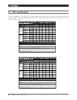
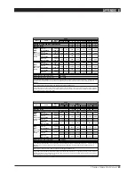
See Appendix to review the table containing Gain
versus VPL setting implications for input sensitivity
and output power.
Bridge mode operation automatically
compensates by -6 dB, keeping all channels
at the same gain.
7.4.4.1 Channel gain/Level (front panel pots)
Individual channel gain (level) may be adjusted using
the potentiometers located on the front panel behind
the dust-filter cover. Range is from 0 dB to -Infinity
in 21 steps. The attenuation is logarithmic, with the
12 o’clock position indicating -10 dB.
Use your fingers or a screwdriver to adjust the
potentiometers.
If the level control is used to attenuate to
a lower level than the headroom relative to
input sensitivity AND the amplifier input is
driven into clip, there is a danger of clipping
the input stage before the current or voltage peak
limiters are activated.
7.4.4. Amplifier sensitivity
Sensitivity is defined as how many Volts (rms) or
dBu (referred to 0.775 Vrms) are required to achieve
full (maximum) output power. As the output power
varies with the load impedance, 4 ohms is usually
the common reference.
Since C Series amplifiers are capable of providing
multiple maximum output power levels through use
of the VPL feature, many sensitivity calculations
may be required for a single amplifier. We recom-
mend use of the DeviceControl editor to simplify this
process. DeviceControl’s device view page, used in
combination with the DIP switch settings display,
will automatically produce a sensitivity calculation
from the given data (VPL, Gain and load).
7.4.5 Output Voltage Peak Limiter (VPL)
Voltage Peak Limiter (VPL) is a unique feature in C
Series amplifiers. It is used to select the maximum
power available on each output channel. Eight levels
can be set using the DIP switches on the amplifier’s
rear panel.
V
peak
V
rms
141
100
118
84
100
70
85
60
71
50
59
42
50
35
42
30
The values for VPL are displayed as maximum Voltage
Peak. To translate Voltage Peak into V
rms
, you must
divide the Voltage Peak values by 1.41 (see table).
The VPL allows you to set the correct maximum
output peak power for optimum performance with the
connected speakers. The correct setting depends on
the system type (lo-or hi-impedance) and the specific
load connected to the channel. Since each channel
can be configured to deliver either very high voltage
peak power OR high current draw at low impedances,
it is important to set the VPL correctly.
To configure an individual output channel for a
constant voltage system, you simply adjust the DIP
switches to the desired voltage. However, when
using an output for a low impedance system (2,
4, 8 or 16 ohms), then sometimes you need to
adjust the VPL to a lower setting to avoid either
delivering excessively high continuous power to the
OPERATION AND PERFORMANCE 7
Summary of Contents for C 68:4
Page 13: ...C Series Operation Manual 13...


