background image

10  

FP+ Series Operation Manual 

6  QUICK GUIDE OVERVIEW

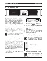
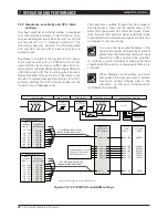
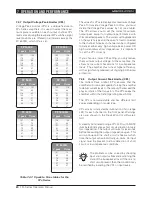
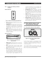
The amplifier’s front panel presents the performance 

and fault condition indicators, power and remote 

switches, and a removable dust-filter cover. Level 

potentiometers provide individual attenuation for the 

amplifier channels. Range is 0 dB to - infinity. (The 

12 o’clock position indicates -10 dB attenuation.) A 

convenient label strip with writing surface is provided 

adjacent to each level potentiometer.  

To remove the dust-filter covers, loosen the thumb-

screws located underneath the front handles. This 

allows removal of the dust-filters for cleaning. The 

covers may be made “tamper resistant” by replacing 

the thumbscrews with Philips head or safety Torx 

screw. Thread size is M3. 

The amplifier never should be operated 

without the dust-filters in place.

6.1.1  Power on/off and remote switch

The Power on/off switch is located on the right side. 

A second switch, labeled “REMOTE,” is above the 

Power switch. When the Remote switch is on (with 

mains connected and power on/off switch on), the 

yellow LED above it will illuminate indicating that  

external power on/off commands from the NomadLink 

network connection will switch the amplifier on or 

off. When Remote is activated the amplifier will not 

switch on until a “Power On” command is received 

from the network. When the remote switch is off, 

it is not possible to switch amplifier power on or off 

using NomadLink network control.  

6.1.2  front-panel LEd’s

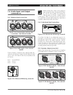
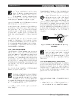
The  front-panel  LED  area  includes  the  following 

indicators per channel:


VHF

TEM

NOMAD

    LINK

BRIDGE C+D

SIG   -20   -15   -10 -4 VPL CPL

SIG   -20   -15   -10 -4 VPL CPL

BRIDGE A+B

MUTE

MUTE

SIG   -20   -15   -10 -4 VPL CPL

SIG   -20   -15   -10 -4 VPL CPL


HI-IMP

HI-IMP

HI-IMP

HI-IMP

CLIP

CLIP

CLIP

CLIP

VHF

TEM

VHF

TEM

VHF

TEM

PWR

PAL

FP10000Q

-10dB

-inf

0

-10dB

-inf

0

-10dB

-inf

0

-10dB

-inf

0

channel

A

B

channel

C

channel

D

channel

FP SERIES

R

POW

POW

6.1  front-Panel overview


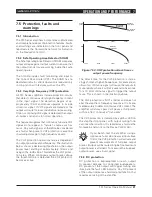
Figure 6.1.2a: Front panel LED field (per-

channel)

Vhf


 - Very High Frequency protection active (output muted) 

(Yellow constant)

TEM


 - Temperature warning (Yellow flashing) 

TEM


 - Temperature mute (Yellow constant)

MuTE


 - Channel muted via NomadLink network or due 

to a fault condition (Red)

CPL


 - Current Peak Limiter (CPL) active (Orange flashing) 

CPL


 - (Orange constant with output muted): Low impe-

dance / short circuit detection fault  

VPL


 - Voltage Peak Limiter (VPL) active

SIG


 - Signal levels - 40 dB (Sig) to –4 dB 

hi-Imp


 - High-impedance/open load detected (Orange) 

Bridge


 - Bridge mode operation (Yellow)

.

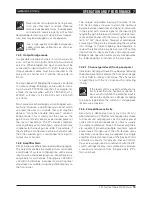
When no VPL, CPL or PAL indicators are illumi-

nated, and the VPL DIP-switch is set to maximum 

at  the  specified  nominal  load,  the  amplifier 

channel is able to deliver maximum rated output 

power 


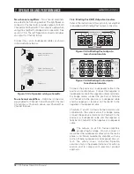
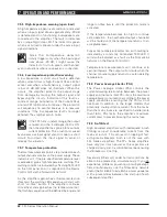
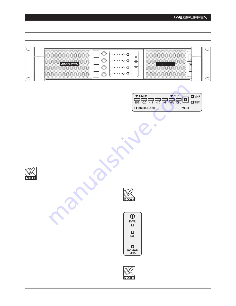
(PWR) Power on (Green) 

(PAL) Power Average Limiter active 

(Red) 

NomadLink network active (Blue)

Figure 6.1.2b: Front panel global LED field

When  the  network  is  connected,  the  blue  

NomadLink LED will illuminate even when mains 

power is not connected. NomadLink receives 

phantom power from the network as supplied 

by the NLB 60E.

Summary of Contents for FP14000

Page 1: ...FP Series Dedicated Touring Amplifiers Rev 1 0 5 Item no OM FP Operation Manual...

Page 2: ...Peak Limiter VPL 6 4 2 4 Protection and performance optimization 6 4 2 5 NomadLink Ethernet control and monitoring network 7 5 installation 8 5 1 Unpacking 8 5 2 Mounting 8 5 2 1 Rear support bracket...

Page 3: ...VHF protection 21 7 5 4 DC protection 21 7 5 5 High impedance warning open load 22 7 5 6 Low impedance protection short circuit 22 7 5 7 Temperature protection 22 7 5 8 Power Average Limiter PAL 22 7...

Page 4: ...he manufacturer 11 The unit is intended to use in a 19 rack Follow the mounting instructions When a rack on wheels is used use caution when moving the loaded rack to avoid injury from tipping over 12...

Page 5: ...to radio or television reception which can be deter mined by turning the equipment on and off the user is encouraged to try to correct the interference by one or more of the following measures Reorie...

Page 6: ...ted Class TD amplifier and Regulated Switch Mode Power Supply R SMPS Lab gruppen s patented Class TD technology combines the exceptional efficiency of a Class D amplifier with the high sonic quality a...

Page 7: ...ed amplifiers The patented network topology provides automatic detection and addressing of multiple amplifiers and is controlled from a PC via the optional NLB 60E NomadLink Bridge Network Controller...

Page 8: ...during shipping Save the carton and packing materials for the carrier s inspection Should you ever need to ship the amplifier always use the original packaging materials 5 2 Mounting Free airflow fro...

Page 9: ...ar of the amplifier indicates the AC mains voltage for which the amplifier is wired and approved 115 V or 230 V Connect the power cable only to the AC source type referred to on the label The warranty...

Page 10: ...wer on or off using NomadLink network control 6 1 2 Front panel LED s The front panel LED area includes the following indicators per channel VHF TEM NOMAD LINK BRIDGE C D SIG 20 15 10 4 VPL CPL SIG 20...

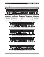
Page 11: ...n EtherCon housed RJ45 connections 4 channel version shown with Neutrik Speakon output connectors Rear view of two channel model fitted with Binding Post connectors Rear view of two channel model fitt...

Page 12: ...vary by model within the FP Series Mode Select VPL mode to either Hard or Soft operation For channels driving sub woofers and low frequency drivers it is recommended to use the Hard setting for optima...

Page 13: ...rs SP The FP 9000 FP 13000 and FP 14000 are offered with BP connectors only as the potential maximum output current exceeds the recommended limits for the Speakon connectors For specific configuration...

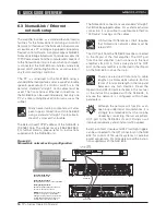
Page 14: ...mplifier s IN port to form a daisy chain The OUT port on the last amplifier is connected to the IN port on the NLB 60E to close the loop There are electrical limitations to cable lengths on a NomadLin...

Page 15: ...ese sensing circuits are also employed to feed back voltage and current level information via a side chain to the limiters Sensing circuits also transmit local amplifier module temperature and power s...

Page 16: ...ping the input stage before the current or voltage peak limiters are activated When bridging two channels you must add 6 dB to the input sensitivity to achieve maximum output voltage due to the automa...

Page 17: ...ource e g a DSP crossover unit can drive up to four amplifier channels before external line drivers might be required to buffer the signal 7 4 2 Unbalanced Input connections Figure 7 4 2 Unbalanced XL...

Page 18: ...connectors Figure 7 4 4a Binding Post outputs two channel models Figure 7 4 4b Binding Post outputs four channel models Connect the positive loudspeaker cable to the positive red terminals Connect th...

Page 19: ...dB to 44 dB in 3 dB steps Individual channel fine level adjustment is available using the potentiometers on the front panel The unique adjustable input gain feature of the FP Series makes it easier t...

Page 20: ...is important to set the VPL correctly If you choose a lower VPL setting you only reduce the maximum output voltage At the same time this allows more current headroom for low impedance loads The ampli...

Page 21: ...and rising with a 6 dB slope This defines the VHF protec tion area When continuous output power above the threshold line is detected the VHF protection becomes active 20 Hz 10 kHz 20 kHz 30 kHz 6 dB...

Page 22: ...etwork As the amplifier approaches a thermal protection threshold the warning LED sequence will start with short on time bursts If the amplifier continues to overheat and approaches the temperature li...

Page 23: ...ected More detailed signal indications are available using the DeviceControl software application 7 6 2 Level adjust Level adjust potentiometers one per channel are located on the front panel adjacent...

Page 24: ...D will illuminate and the output will mute for 6 seconds before re measuring the output impedance This will continue until the short circuit is removed CPL remains constant orange in a fault condition...

Page 25: ...rnet cables should be used To ensure full performance of your NLB 60E NomadLink Bridge Network Controller with the expanded range of FP Series amplifiers as well as full compatibility with Lab gruppen...

Page 26: ...pen s proprietary software application for monitoring and controlling networked FP Series and other Lab gruppen NomadLink ready power amplifier DeviceControl runs on a Windows PC which connects via Et...

Page 27: ...amplifier General rules of cable lengths The maximum cable length in between any two devices may not exceed 300 meters 980 feet In a non closed loop daisy chained subnet the maximum cable length is 4...

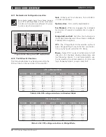
Page 28: ...600 759 809 2589 2762 652 696 16 Bridged 4700 x 1 4 Ch 4400 x 2 30 0 16 0 2320 2474 1463 1560 857 914 2926 3121 737 786 8 Bridged 8800 x 1 2 Ch 7000 x 2 30 0 16 0 2277 2429 1266 1350 1012 1079 3453 36...

Page 29: ...230 V CE version 16 A CEE7 Mains connector 115 V ETL version 30 A Twist lock 1 The amplifier s PSU operates as a non resistive load so the calculation Volts x Amps Watts would not be correct Instead m...

Page 30: ...d 6000 x 1 2 Ch 4500 x 2 30 0 16 0 2258 2409 1219 1300 1039 1109 3548 3784 894 953 4 Bridged 9000 x 1 Mains connector 230 V CE version 16 A CEE7 Mains connector 115 V ETL version 30 A Twist lock 1 The...

Page 31: ...6 8 Bridged 5600 x 1 2 Ch 3500 x 2 30 0 16 0 2316 2380 1526 1586 790 794 2696 2710 679 683 4 Bridged 7000 x 1 Mains connector 230 V CE version 16 A CEE7 Mains connector 115 V ETL version 30 A Twist lo...

Page 32: ...200 x 1 2 Ch 2000 x 2 28 6 14 9 2226 1533 692 2363 595 4 Bridged 4000 x 1 Mains connector 230 V CE version 16 A CEE7 Mains connector 115 V ETL version 20 A Nema 5 20P 1 The amplifier s PSU operates as...

Page 33: ...164 3973 1001 4 Bridged 4 5000 x 2 Pink noise max power 3 16 Ch 660 x 4 13 6 7 1 1143 880 263 897 226 32 Bridged 1320 x 2 8 Ch 1300 x 4 22 4 11 7 2096 1733 363 1238 312 16 Bridged 2600 x 2 4 Ch 2100 x...

Page 34: ...Ch 1500 x 4 30 0 16 0 2244 2300 1329 1384 915 916 3122 3125 786 787 4 Bridged 3000 x 2 Mains connector 230 V CE version 16 A CEE7 Mains connector 115 V ETL version 30 A Twist lock 1 The amplifier s PS...

Page 35: ...tor 230 V CE 16 A CEE7 115 V ETL 30 A Twist lock FP 4000 230 V CE 16 A CEE7 115 V ETL 20 A NEMA 5 20P dimensions W h d W 483 mm 19 H 88 mm 2 U Overall D 396 mm 15 6 Mounting D 358 mm 14 1 Weight 12 kg...

Page 36: ...due to cancellation of any events or rent of replace ment equipment or costs due to a third party s or customer s loss of profit or any other indirect cost or losses however incurred Lab gruppen reser...

Page 37: ...L a b g r u p p e n AB S w e d e n i n t e r n a t i o n a L c o n t a c t i n f o L a b g r u p p e n c o m U S CANADA CONTACT i n f o TCG AMERICA S c o m w w w l a b g r u p p e n c o m...

Reviews: