FP+ Series Operation Manual
15
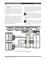
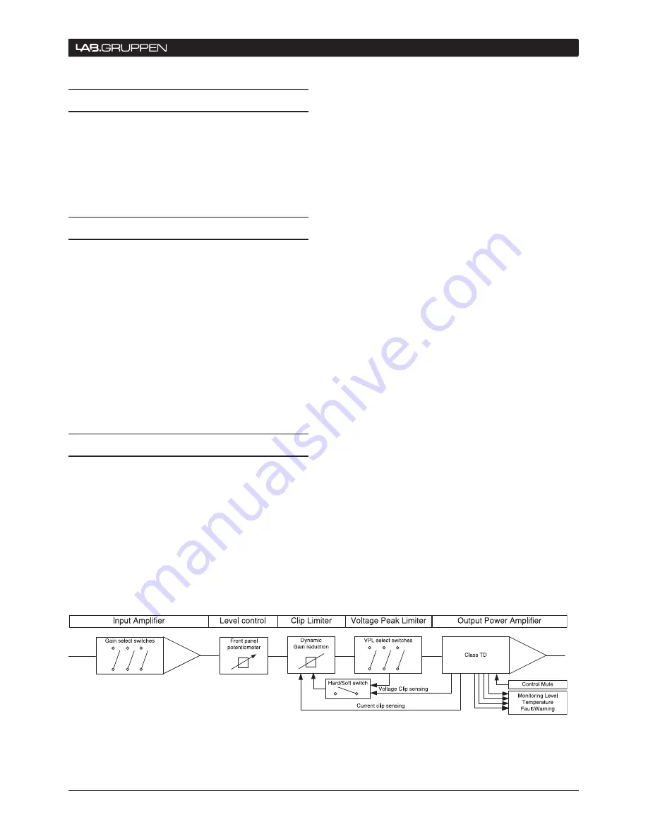
Overall amplifier input gain is adjusted using the
input stage DIP-switches. Please note that the gain
setting is global, affecting all channels. Following
the input stage, the dedicated level control on each
channel allows signal attenuation from 0 dB to minus
infinity.
The Current Peak Limiter (CPL) section dynamically
limits the input signal based on three parameters:
sensed current level, feedback from the output stage,
and sensed voltage clip from the VPL (and output
amplifier voltage clip if “Soft Clip” is activated). This
ensures that power output is maintained within the
design limits of the amplifier.
The adjustable Voltage Peak Limiter (VPL) sets the
maximum output voltage and therefore also the
maximum output power. Eight different voltage
stages are available using the DIP-switches on the
rear panel of all models, except the FP 9000 and FP
4000 that both have seven stages and the FP 6000Q
which provides six voltage stages.
The sophisticated output section monitors faults
and generates appropriate warnings, which are
displayed on the amplifier front panel and transmitted
through the NomadLink network. These alerts allow
the operator to adjust system settings and thereby
avoid problems. In the rare event that conditions are
extraordinarily severe, the amplifier will shut down
until the fault or problem setting has been rectified
or adjusted. These sensing circuits are also employed
to feed back voltage and current level information,
via a side chain, to the limiters. Sensing circuits
also transmit local amplifier module temperature
and power supply temperature to the appropriate
protection mechanisms. Read the Protection, Faults
and Warnings section for further details.
7.1 Introduction
The following sections provide comprehensive
information on amplifier connection, setup, operation,
and performance. The detailed information included
here is essential to realizing the full functionality of the
FP+ Series amplifiers.
7.2 Operation precautions
Make sure that the Power switch and the Remote
▸
switch on the amplifier front panel are set to
“off” before making any input, output or network
connections, and also before manipulating the
DIP-switches on the rear panel.
Make sure that the AC mains voltage is correct
▸
and matches the voltage printed on the rear panel
of the amplifier (115 V or 230 V).
Make sure that no signal is present at the input
▸
to the amplifier when powering up. An input
signal could produce an unintentionally loud initial
volume from the speakers.
7.3 Signal flow and headroom
7.3.1 Signal flow blocks
All FP+ Series amplifiers have the same signal flow,
and the same feature sets. The only internal differ-
ences are in the maximum output current per channel
and VPL settings.
The input stage of all FP+ Series amplifiers has a
high sensitivity to provide ample system headroom.
This in effect means that the input stage is almost
impossible to clip.
OPERATION AND PERFORMANCE 7
Figure 7.3.1: FP+ Series signal flow diagram

