32
FP+ Series Operation Manual
8 APPENDIX
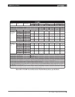
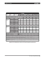
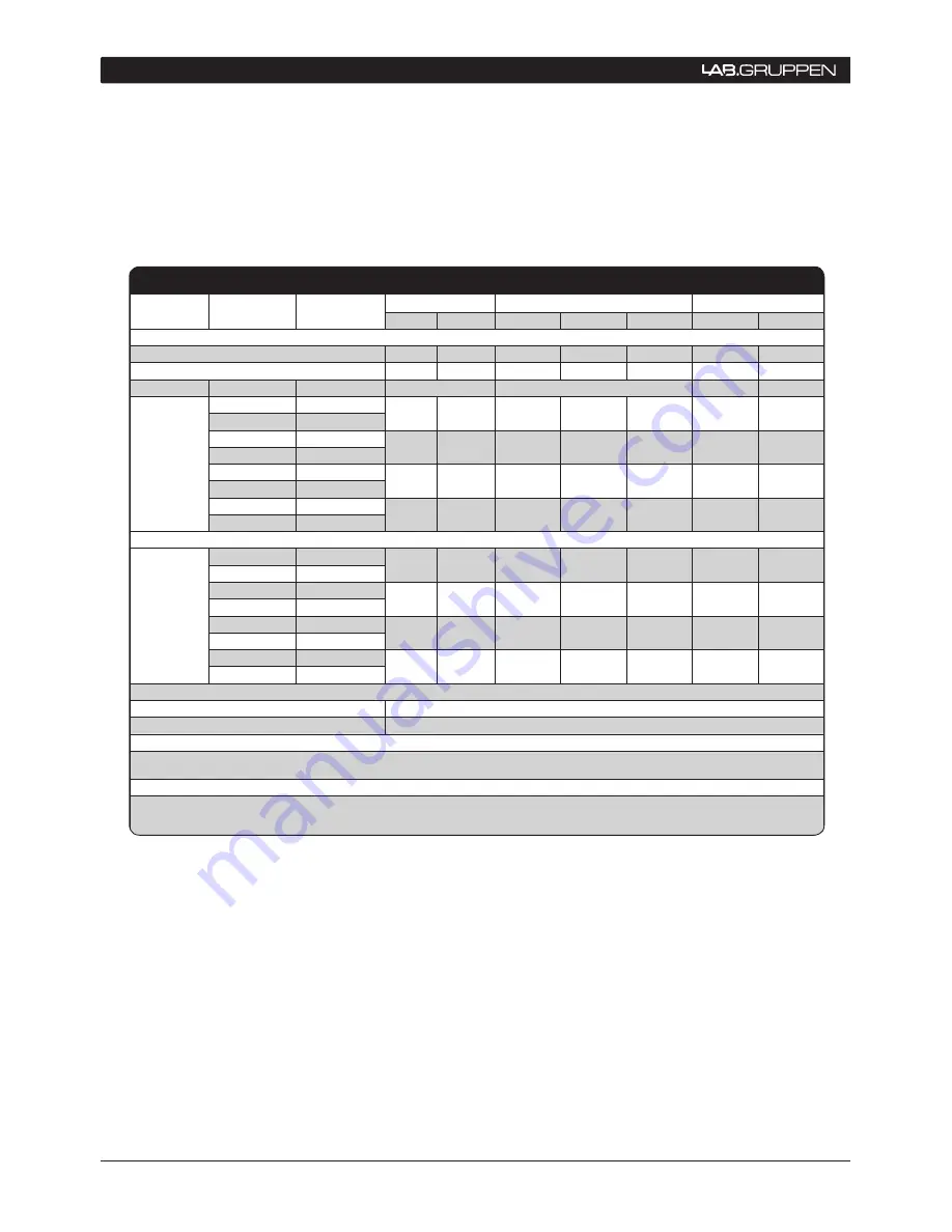
FP 4000
Level
Load
Rated power
Line Current *2)
Watt *1)
Thermal dissipation
120 VAC
230 VAC
In
Out
Dissipated
BTU/hr
kCal/hr
Standby with remote power off via Nomadlink
®
0.1
0.2
0
0
1
0
Power on, Idling
0.8
87
0
87
298
75
Amp (I)
Watt
Pink noise
(1/8th rated
power)
16 Ω / Ch.
400 x 2
3.9
2.0
262
100
162
552
139
32 Ω / Bridged
800 x 1
8 Ω / Ch.
800 x 2
6.1
3.2
424
200
224
765
193
16 Ω / Bridged
1600 x 1
4 Ω / Ch.
1600 x 2
10.7
5.6
782
400
382
1305
329
8 Ω / Bridged
3200 x 1
2 Ω / Ch.
2000 x 2
14.2
7.4
1035
575
460
1569
395
4 Ω / Bridged
4000 x 1
Pink noise
(max power)
*3)
16 Ω / Ch.
400 x 2
7.0
3.7
499
267
232
793
200
32 Ω / Bridged
800 x 1
8 Ω / Ch.
800 x 2
12.1
6.3
893
533
359
1227
309
16 Ω / Bridged
1600 x 1
4 Ω / Ch.
1600 x 2
21.7
11.3
1681
1067
615
2098
529
8 Ω / Bridged
3200 x 1
2 Ω / Ch.
2000 x 2
28.6
14.9
2226
1533
692
2363
595
4 Ω / Bridged
4000 x 1
Mains connector, 230 V CE version
16 A, CEE7
Mains connector, 115 V ETL version
20 A, Nema 5-20P
*1) The amplifi er’s PSU operates as a non-resistive load, so the calculation “Volts x Amps = Watts” would not be correct. Instead, measured and specifi ed here
is what is known as the “Active Power” of the amplifi er providing useful, real-world values of power consumption and heat dissipation.
*2) Current draw fi gures measured at 230 V. 115 V fi gures are 230 V fi gures multiplied by two.
*3) Figures measured at maximum sustainable power without tripping the mains fuse. Listed separately for 30 A/115 V and 16 A/230 V operation . Note that
the max. power condition is very extreme and will not occur during normal operation. Also note that the mains breaker will not be tripped even if operation is
momentarily
in excess of max. ratings.
Table 8.4e: FP 4000 Current Draw and Thermal Dissipation specifications

