background image


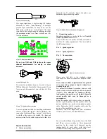
Please refer to diagram on page 3 

 
1. Speaker 

connector 

This type of speaker connector may be unfamiliar to 
some users. A full description is found in the 
operation section. (See page 6). 

 
2.  Clip limiter switch. 

Turns the clip limiter on and off. 

 
3. Input 

jack 

Alternative to using input XLR or for linking inputs 
with other amplifiers. (See page 5). 


4. 

Input  signal XLR 

(See page 5).


5.  Phase reverse switch for channel B 

For reversing the input signal phase of channel B to 
allow bridged operation. (See page 7). 

 
6. Link 

switch 

Allows a single input to drive both channels 
simultaneously. (See page 7). 
 

7.  Gain select switch 

Allows amplifier gain to be switched between 29dB 
and its normal gain at 0.775mV input sensitivity. 
(See page 7). 


8. 

AC line cord 

(See page 5).


Installation 

1. Mounting 

The amplifier is two rack units high (2U) and will 
mount in a standard EIA 19 inch rack. Amplifiers 
may be stacked directly on top of each other. There 
is no need for spacing between units. If it is the 
intention to fill a rack with amplifiers, we 
recommend racking is started from the bottom of 
the rack. It is also recommended that rear supports 
are used for amplifiers mounted in the middle of the 
rack, especially if used as part of a portable system. 
 

2.  

Cooling 

Your amplifier uses forced air cooling system to 
maintain a low and even operating temperature. All 
LAB.GRUPPEN amplifier, which are fan 
ventilated, have front to rear cooling. There are 
several reasons for this, one is that there's usually 
cooler air outside the rack than inside and therefore 
the amplifiers can run at higher continuos power 
levels without thermal problems. Never try to 
reverse the air flow, as the Intercooler® need a 
pressure chamber between the fans and heat sink, 
and this only works in one direction of the air flow 
(see Design features on page 8).


Should a heat sink get too hot, its sensing circuit 
will mute the hot channel. If the power supply 
overheats, another sensing circuit will mute all 
output channels, until it cools down to a safe 
operating temperature. 
Make sure that there is an adequate air supply in 
front of the amplifier and that the rear of the 
amplifier has sufficient space to allows the exhaust 
to escape. If the amplifier is rack mounted, do not 
use covers or doors on the front or rear of the rack.  
For fixed installations with a central cooling 
system, usually found in fixed installations with a 
dedicated rack room, it may be necessary to 
calculate the maximum heat emission. Refer to 
Power consumption on page 5. 

 
3.   Operating voltage 

A label just below the mains cable on the rear of 
the amplifier indicates the AC mains voltage, for 
which the amplifier is wired. Connect the power 
cable only to the AC source referred to on the label. 
The warranty will not cover damage caused by 
connecting to the wrong type of AC mains. 
For converting a 230 volt amplifier to 115 volt or 
vice-versa, see Appendix A.  
LAB.GRUPPEN switch mode amplifier use 
primary switching, i.e. the mains is rectified 
directly before the transformer, which means that 
the power supply is insensitive to the mains 
frequency and will operate from DC to 400 Hz. 
The amplifier is supplied with an approved European 
AC line connector. If this connector is not 
appropriate for your country, it can be cut off and 
wired to a suitable connector in the following way : 
 

BROWN   LIVE 
 
BLUE 

  NEUTRAL 

 
GREEN/YELLOW EARTH 

 
Once the AC connector is connected to a suitable AC 
supply, the amplifier can be started with the AC 
actuator.  
When you power up the amplifier it takes a couple of 
seconds to check its circuits (this is known as the 
"soft start" or "slow start" sequence), the fans then 
blow at high speed before going onto "idle" and the 2 
bottom green LED’s come on to show the output 
circuits are receiving the correct rail voltage. 

 
4.   Grounding 

There is no ground lift switch or terminal on this 
amplifier. The signal ground is always floating via a 
resistor to chassis and the grounding system is 
automatic. If a potential above 0.6V presents itself 
between signal ground and chassis ground, a short 
circuit is introduced between the two, thereby 
enabling electrical protection. If a unit in the system 


4

Summary of Contents for LAB 1300C

Page 1: ...on 7 1 Operation precautions 2 Powering up Soft start 3 Input attenuators 4 Gain switch 5 Indicators Protections 8 1 Clip limiter 2 Thermal protection 3 VHF protection 4 Short circuit protection 5 AC mains voltage protection 6 D C protection LAB 1300C USER MANUAL Design features 9 Cooling Light weight Regulated power supply Safety approvals EMC approvals Specifications 10 EMC declaration Appendix ...

Page 2: ...oth loudspeakers and humans alike Many loudspeakers can be easily damaged or destroyed by overpowering especially with the high power available from a bridged amplifier Always check the speakers continuous and peak power capabilities Even if the gain is reduced by using the amplifier s front panel attenuator it is still possible to reach full output power if the input signal level is high enough 2...

Page 3: ...ate above its maximum operating temperature 90o C The indicator first comes on as a warning to either turn down the input level or check the cooling arrangements after which point the amplifier will mute the input signal When the cooling fans have returned the output heat sinks to the normal operating temperature the input signal is unmuted 4 VHF protection indicator This indicator lights when con...

Page 4: ...until it cools down to a safe operating temperature Make sure that there is an adequate air supply in front of the amplifier and that the rear of the amplifier has sufficient space to allows the exhaust to escape If the amplifier is rack mounted do not use covers or doors on the front or rear of the rack For fixed installations with a central cooling system usually found in fixed installations wit...

Page 5: ...h of the total power is as loud as you can play music while making some attempt to avoid obvious clipping It also corresponds to a headroom of 9dB which is very low for an audio program In 2 ohms operation the protection of the amplifier circuit will not permit long term current draw and the component temperature rise will stabilises well below the rating MAX OUTPUT POWER MAINS INPUT POWER Power F...

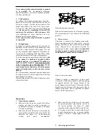
Page 6: ...e two Neutrik NL4FC Speakon connectors 1 They are the only connectors currently available to meet the EC safety requirements They are wired in the following manner Pin 1 Speaker ground Pin 1 Speaker positive Pin 2 No connection Pin 2 No connection Figure 9 Speakon connector Please note that this is the standard wiring convention for Speakon connectors adopted world wide Never connect either output...

Page 7: ...hms Driving bridged loads of less than 4 ohms may cause a thermal overload Figure 10 Bridge mono connection Both level attenuators must be at the same position We recommend you to put them in the 0 dB full position 4 Stereo reverse This mode is similar to the Tandem mono mode Apart from depressing the Link switch you also depress the Phase reverse switch like in the Bridge mono Channel B is now ph...

Page 8: ...below Protection features Each LAB GRUPPEN amplifier has many advanced protection features that will protect both the amplifier and the speakers connected to it should a fault condition arise Under normal use these features are inaudible All protection circuits are independent Clip limiter The clip limiter is included to prevent dangerous clip signals reaching the speaker and damaging it It works ...

Page 9: ...a pressure chamber The air flow is constant along the whole heat sink thanks to a horizontal pressure chamber in front of it in a conventional tunnel design the end of the heat sink opposite to the fan invariably gets hotter than that directly in front of the fan When cool air hits the geometric fins of the IntercoolerTM turbulence is produced thereby enabling efficient cooling Light weight The sw...

Page 10: ...Immunity The equipment should be able to handle three different types of interference Electrostatic discharges up to 8 kV hitting the chassis or cables Transients and bursts up to 1 kV conducted through the cables to the unit Electromagnetic fields up to 3 V m radiated on the unit and the cables in the frequency range of 27 500 MHz We have extended the tests in two cases and chosen a standard used...

Page 11: ...nside of the amplifier These conditions usually occur after prolonged use in environments using cracked oil smoke machines If you are using your amplifier for heavy duty use i e concert touring or industrial music it is recommended that you have your amplifier serviced every 3 years purely as a preventative measure Troubleshooting These are typical things to check if you think your amplifier is fa...

Page 12: ...e 3 LAB GRUPPEN shall not be responsible for any incidental or consequential damages with respect to the products warranted LAB GRUPPEN reserve the right to make changes or improvements in design or manufacturing without assuming any obligation to change or improve products previously manufactured International Please contact your supplier for this information as rights and disclaimers may vary fr...

Reviews: