background image

Chapter 4: Performance Data & Safety Precautions 


Product Service 1-800-522-7658 

26 

Original instructions 


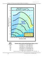
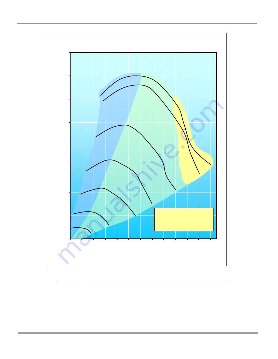
Speed 

(RPM) 


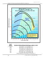
Optimum Airflow (CFM) and Static Pressure (inches of water) 

1800 MAX 

750 CFM @ 1.7" to 1025 CFM @ 1.55" 

1500 

600 CFM @ 1.2" to 1050 CFM @ 0.5" 

1250 

500 CFM @ 0.8" to 850 CFM @ 0.37" 

1000 

400 CFM @ 0.6" to 700 CFM @ 0.25" 

750 

300 CFM @ 0.3" to 475 CFM @ 0.12" 

500 

200 CFM @ 0.12" to 325 CFM @ 0.06" 

300 

175 CFM @ 0.06" to 275 CFM @ 0.04" 


Practical range is 175 CFM, 0.06" to 1025 CFM, 1.5" 


0

0.25

0.5

0.75

1

1.25

1.5

1.75

2

150

250

350

450

550

650

750

850

950

1050 1150 1250 1350

S

tati

P

ressure 

(i

n. 

w

.g.)

Airflow Rate (CFM)

Models 71818-10, -11, -20, -21

120- 240 Volts   10.0 Amps   1 HP

Blower Performance Curve with 10" FRP inlet

500 

750 

1000 

Optimum 

Blower 

Performance

Note:

Ambient Temperatures 

Inside Motor Housing Greater 
than 125 

°F May Reduce 

Maximum Blower Performance

1250 

1500 

1750 

1800 

SEE
NOTE

Summary of Contents for 7061110

Page 1: ...mplete Intelli Sense MSB Blower with Controls Intelli Sense MSB Blower No Controls used for replacement or Integrated Intelli Sense Hoods All 50 60 Hz All 50 60 Hz FRP 10 7181810 115v 20 230v 7181811...

Page 2: ...7 30 a m and 5 30 p m Central Standard Time Part 7115900 Rev I ECO L864 Warranty Labconco Corporation provides a warranty to the original buyer for the repair or replacement of parts and reasonable la...

Page 3: ...ted Steel Blowers 9 Connect Blower Inlet for Fiberglass Blowers 9 Connect Blower Inlet for PVC Blowers 9 Connect PVC Blower Drain 10 Connect to the Blower Outlet 10 For Coated Steel Blowers 13 For Fib...

Page 4: ...41 Auxiliary Air Transition Adaptor 41 T and Y Connections 41 Accessories for Basic 47 Hoods 42 Exhaust Transition Adaptor 42 Accessories for Perchloric Acid Applications 42 Wash Rings 42 Accessories...

Page 5: ...ior roof mounting The blowers also feature forward curved impellers to ensure quiet operation and optimum air delivery All Multi Speed Blowers utilize a direct drive ECM motor that uses 1 3 less energ...

Page 6: ...the unit Si l appareil n est pas utilis comme sp cifi dans ce manuel il peut compromettre la protection offerte par l appareil About This Manual This manual will help you learn how to install use and...

Page 7: ...to the user or permanent damage to the Blower L information critique est pr sent en caract res gras dans les paragraphes qui sont pr c d s de l ic ne d exclamation Le non respect de l information sui...

Page 8: ...face AVERTIR Surface Chaude If you would like to review how blowers operate or their differentiating features go to Chapter 4 Performance Data and Safety Precautions For information on the operational...

Page 9: ...e requirements for your installation site Refer to Appendix B Blower Dimensions for complete blower dimensions Refer to Appendix C Blower Environmental Conditions for complete environmental conditions...

Page 10: ...he instruction manual cover and in the charts in Chapter 4 Performance Data and Safety Precautions All MSB blowers operate at a maximum of 10 full load amps for 115V and 6 full load amps for 230V Cont...

Page 11: ...l the MSB Control Box Adjust the fan speed and confirm blower performance Connect the PVC Blower drain PVC Blowers only Unpacking Your Blower Carefully remove the shipping carton from your blower Insp...

Page 12: ...Blower Dimensions for appropriate mounting hole locations for your particular blower Adjust the Blower Outlet Orientation The housing on your blower can be rotated to facilitate your duct run configu...

Page 13: ...iameter PVC ductwork will fit over the inlet ring on the blower and should be fastened in position by sheet metal screws into the metal ring Connect to the Blower Inlet for Fiberglass Blowers 10 Fiber...

Page 14: ...aison des produits chimiques corrosifs puis Connect to the Blower Outlet Before proceeding with the blower outlet connection read the two warnings and follow the suggested pictures listed next WARNING...

Page 15: ...structural support Structural support is connected to C clamp coupler Note Duct diameters duct materials and heights change and Labconco does not carry the structural supports or guy wires Guy wires f...

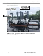
Page 16: ...stallation Picture 4 Note Duct diameters duct materials and heights change and Labconco does not carry the structural supports or guy wires Five Typical Blowers Typical 3 piece turnbuckle connected to...

Page 17: ...metal screws through the housing Silicone sealant should be used to seal any air leaks between the duct and blower outlet connection 12 Fiberglass Blowers feature a 12 3 4 ID outlet connection Twelve...

Page 18: ...V harness is 7115300 and the 230V harness is 7115301 per wiring diagrams in Appendix C ATTENTION V rifiez la tension nominale ventilateur MSB et le num ro de mod le attentivement avant de brancher vot...

Page 19: ...circuitry to vary the speed and set up the fume hood for two or three speed operation If desired the MSB can still be set up for simple ON OFF operation The three switch options are listed below and...

Page 20: ...the monitor cable terminals 8 Install the new blower switch label blower switch and blower switch retainer If needed blower switch cutout is 0 83 x 1 45 2 1 cm x 3 7 cm 9 Connect the MSB Control Cabl...

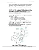
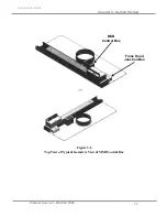
Page 21: ...Chapter 3 Getting Started Product Service 1 800 522 7658 17 Original instructions Figure 3 2 Top View of Typical Isometric View of MSB Control Box MSB Control Box Fume Hood Junction Box...

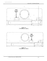
Page 22: ...Chapter 3 Getting Started Product Service 1 800 522 7658 18 Original instructions Figure 3 3 3 Installation Location Figure 3 4 4 Installation Location MSB Control Box MSB Control Box...

Page 23: ...Chapter 3 Getting Started Product Service 1 800 522 7658 19 Original instructions Figure 3 5 5 Installation Location Figure 3 6 6 Installation Location MSB Control Box MSB Control Box...

Page 24: ...Chapter 3 Getting Started Product Service 1 800 522 7658 20 Original instructions Figure 3 7 7 Installation Location Figure 3 8 8 Installation Location MSB Control Box MSB Control Box...

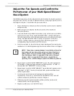
Page 25: ...e 4 It will be necessary to check the blower wheel shaft speed by removing the weathercover to confirm operation per the blower airflow charts in Chapter 4 HINT Many times a manual damper is used in t...

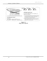
Page 26: ...Chapter 3 Getting Started Product Service 1 800 522 7658 22 Original instructions Figure 3 9 Adjust the Fan Speeds...

Page 27: ...rflow of 1100CFM 12 Blower 200 495 200 735 200 955 200 1180 200 1410 200 1410 200 1410 200 1410 200 1410 Airflow Range CFM Note 12 Blowers have a minimum achievable airflow of 200CFM and a maximum air...

Page 28: ...00 CFM 0 20 to 450 CFM 0 10 300 175 CFM 0 06 to 350 CFM 0 08 Practical range is 175 CFM 0 06 to 1050 CFM 1 9 or 1200 CFM 1 0 0 0 25 0 5 0 75 1 1 25 1 5 1 75 2 2 25 2 5 150 250 350 450 550 650 750 850...

Page 29: ...200 CFM 0 08 to 450 CFM 0 1 Practical range is 200 CFM 0 08 to 1350 CFM 1 5 or 1450 CFM 1 2 0 0 25 0 5 0 75 1 1 25 1 5 1 75 2 2 25 150 250 350 450 550 650 750 850 950 1050 1150 1250 1350 1450 1550 Sta...

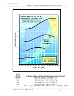
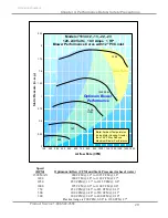
Page 30: ...75 CFM 0 12 500 200 CFM 0 12 to 325 CFM 0 06 300 175 CFM 0 06 to 275 CFM 0 04 Practical range is 175 CFM 0 06 to 1025 CFM 1 5 0 0 25 0 5 0 75 1 1 25 1 5 1 75 2 150 250 350 450 550 650 750 850 950 1050...

Page 31: ...CFM 0 34 500 300 CFM 0 20 to 575 CFM 0 12 300 200 CFM 0 08 to 450 CFM 0 10 Practical range is 200 CFM 0 08 to 1400 CFM 0 87 or 1150 CFM 1 4 0 0 25 0 5 0 75 1 1 25 1 5 1 75 2 2 25 150 250 350 450 550...

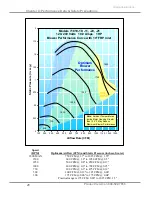
Page 32: ...200 CFM 0 12 to 350 CFM 0 06 300 175 CFM 0 06 to 275 CFM 0 04 Practical range is 175 CFM 0 06 to 1100 CFM 1 3 0 0 25 0 5 0 75 1 1 25 1 5 1 75 2 150 250 350 450 550 650 750 850 950 1050 1150 1250 1350...

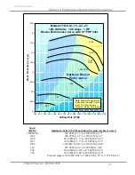
Page 33: ...0 33 500 300 CFM 0 20 to 550 CFM 0 12 300 200 CFM 0 08 to 400 CFM 0 10 Practical range is 200 CFM 0 08 to 1180 CFM 1 7 0 0 25 0 5 0 75 1 1 25 1 5 1 75 2 2 25 150 250 350 450 550 650 750 850 950 1050...

Page 34: ...e it is initially used The blower hood system should be re certified annually or whenever it is relocated Avant de proc der un entretien et ou de maintenance sur votre ventilateur d branchez toujours...

Page 35: ...utlined in Chapter 8 For night set back to save energy fully lower the fume hood sash and select the lowest switch setting Always monitor your airflow constantly with a fume hood airflow monitor For b...

Page 36: ...Chapter 5 Using Your Blower Product Service 1 800 522 7658 32 Original instructions...

Page 37: ...wrench icon precedes the service operations that require qualified technicians Routine Maintenance CAUTION Before attempting any service and or maintenance on your blower always disconnect the unit fr...

Page 38: ...ring on your blower make sure that the locking collars on the bearings face one another The setscrews used on the locking collars have been sealed with a removable thread sealant Thread sealant should...

Page 39: ...ert the operator to low airflow conditions From the monitor s face plate the user can easily select and calibrate a set point between 30 and 250 fpm using a velocity meter and a screwdriver Audible vi...

Page 40: ...Appendix C and item 17 in Appendix A Two Main Blower Modifications There are two main ways to modify the performance of your blower as listed in Chapter 3 Getting Started One way is the adjustment of...

Page 41: ...ance data in Chapter 4 for Coated Steel Blowers Refer to the 0 25 to 50 range at 725 CFM since this is closest to 0 314 The chart will lead you to select a Coated Steel Blower model that is 10 set at...

Page 42: ...both locations is recommended for noise reduction Zero Pressure Weathercap Thermoplastic Duct Intelli Sense Coated Steel Fiberglass or PVC Blower Flexible Duct Connection Thermoplastic Duct Thermoplas...

Page 43: ...t Duct 0 0 0 0 0 Duct Couplings Male PVC duct in 6 length facilitates connections between Coated Steel Blowers and elbows thermoplastic duct reducers and weather caps Nominal Diameter Inches 6 8 10 12...

Page 44: ...40 Equivalent Resistance in feet of Straight Duct 5 5 5 5 5 Spiral Tube This spiral tube simplifies temporary installations It is corrosion resistant neoprene impregnated fiberglass reinforced with st...

Page 45: ...er Inches 8 10 12 Catalog Number 47224 4722401 70034 Shipping Wt lbs 3 4 4 For use with Labconco Blowers 70680 70687 70680 70687 70688 70697 Auxiliary Air Transition Adaptor The auxiliary air transiti...

Page 46: ...Catalog Number 47460 47461 Shipping Wt lbs 5 6 Accessories for Pathogens Organic Vapors and Odor Control Applications HEPA Filter Packs High Efficiency Particulate Air Filter for non radioactive part...

Page 47: ...osition when the hood is not in use and rises from the airflow exhausting when the blower is on It mounts vertically on blower outlet The damper is made of PVC Type 1 unplasticized schedule 40 duct No...

Page 48: ...Chapter 7 Modifying Your Blower Product Service 1 800 522 7658 44 Original instructions...

Page 49: ...or I S Hoods with limit switches are only available from the factory due to the wiring complexity The integrated Protector I S Hood models with limit switches automatically regulate the Intelli Sense...

Page 50: ...itches for automatic Intelli Sense Blower operation INTEGRATED Minimal set up pre mounted multi speed MSB controller and pre wired limit switches INDEPENDENT No conscious control as blower speeds chan...

Page 51: ...and set to activate with sash raised 20 above work surface The upper limit switch can be lowered in 1 increments between 15 and 20 Red wire to common White wire to normally open Intelli Sense Control...

Page 52: ...Chapter 8 Protector I S Hood Product Service 1 800 522 7658 48 Original instructions Red wire to common Left side lower limit switch wired for low speed Black wire to normally open...

Page 53: ...ns Airflow monitor in line sensor air pathway and wiring to monitor Night setback lower switch shown on right Switch is wired to normally open and common terminals and wired to air monitor input I P1...

Page 54: ...Chapter 8 Protector I S Hood Product Service 1 800 522 7658 50 Original instructions Front of airflow monitor showing SETBACK when sash is closed...

Page 55: ...r 8 Protector I S Hood Product Service 1 800 522 7658 51 Original instructions Back of airflow monitor night setback switch wiring to I P1 for Input 1 Sensor wiring in to air monitor Power in to air m...

Page 56: ...n top of fume hood connection of switch control wires and connection of shielded control wires from roof blower If needed replace control box on top of fume hood Circuit breakers tripped in building e...

Page 57: ...pads to isolate vibration Inspect wheel for damage and appropriate clearance Replace damaged wheel or adjust clearance Check for objects in blower wheel Remove objects in blower wheel Improper inlet c...

Page 58: ...Chapter 9 Troubleshooting Product Service 1 800 522 7658 54 Original instructions...

Page 59: ...Fiberglass FRP 1500 RPM 2E 1 7116205 ECM Motor 1 HP 10 PVC 1900 RPM 2F 1 7116206 ECM Motor 1 HP 12 PVC 1500 RPM 2G 1 7116500 Motor Mounting Bracket 2H 1 7115300 01 Motor Harness to Blower J Box 115V 0...

Page 60: ...Control Box 115V 10 Automatic 9B 1 7115001 20 MSB Control Box 230V 20 Automatic 10 1 7116000 Power Cable Control Box Power Inlet from hood lighting 11A 1 1302401 Blower Switch 3 Position Manually Oper...

Page 61: ...l instructions Figure A 1 4 1 2 1D 3 2H 7 5 Not Shown 6 9 13 14 15 Not Shown 10 16 Not Shown 12 Not Shown 11 8 17 Not Shown 8A Cable Manual Blower Switch to MSB Control Box 8B Cable Automatic Limit Sw...

Page 62: ...Product Service 1 800 522 7658 58 APPENDIX B BLOWER DIMENSIONS...

Page 63: ...Appendix B Blower Dimensions Product Service 1 800 522 7658 59 Original instructions...

Page 64: ...Appendix B Blower Dimensions Product Service 1 800 522 7658 60 Original instructions...

Page 65: ...the nominal voltage Transient over voltages according to Installation Categories II Over voltage Categories per IEC 1010 Temporary voltage spikes on the AC input line that may be as high as 1500V for...

Page 66: ...tal Conditions Wiring Diagrams Product Service 1 800 522 7658 62 Original instructions Wiring Detail Belden 9940 22 GA 4 conductor shielded or equal Alternate Cable harness to limit switches for autom...

Page 67: ...Appendix C Blower Environmental Conditions Wiring Diagrams Product Service 1 800 522 7658 63 Original instructions 115V Wiring Diagram Manual Operation 230V Wiring Diagram Manual Operation...

Page 68: ...Appendix C Blower Environmental Conditions Wiring Diagrams Product Service 1 800 522 7658 64 Original instructions 115V Wiring Diagram Automatic Operation 230V Wiring Diagram Automatic Operation...

Page 69: ...50 Open Red High Data Point H1 895 CFM 1 8 S P 1250 RPM Medium Data Point M1 675 CFM 1 0 S P 895 RPM Low Data Point L1 260 CFM 0 12 S P 330 RPM Damper 75 Open Green High Data Point H2 955 CFM 1 0 S P...

Page 70: ...Appendix D Typical Intelli Sense Blower Operating Curve Product Service 1 800 522 7658 66 Original instructions...

Page 71: ...Product Service 1 800 522 7658 67 APPENDIX E TYPICAL LABORATORY CONTROLS WITH INDIVIDUAL INTELLI SENSE BLOWERS...

Page 72: ...Product Service 1 800 522 7658 68 APPENDIX F TYPICAL PERCHLORIC ACID HOOD INSTALLATION DIAGRAM...

Reviews: