Chapter 7: Modifying Your Blower
Product Service 1-800-522-7658
36
Original instructions
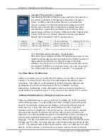
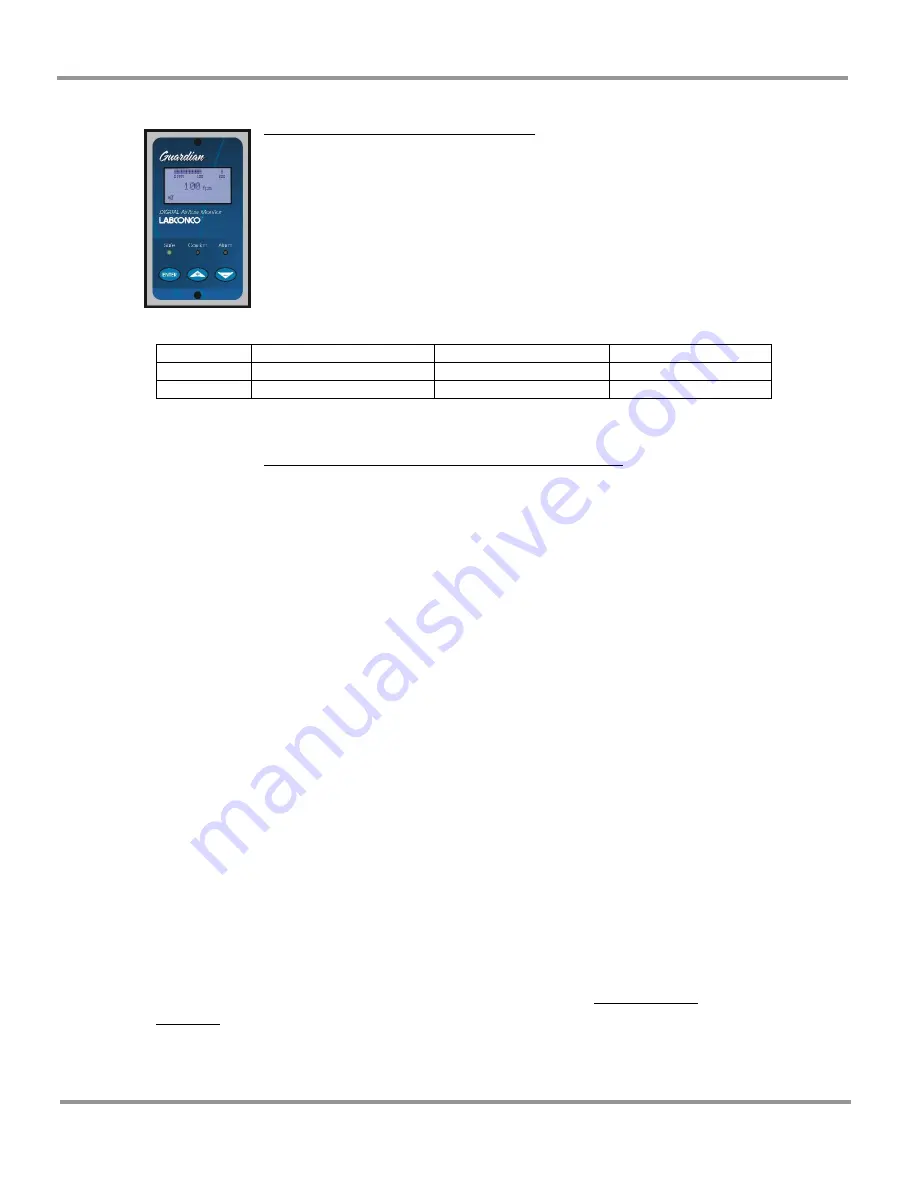
Guardian™ Digital Airflow Monitors
Guardian Digital Airflow Monitor senses and alerts the operator to
low airflow conditions. LCD displays actual airflow in fpm or
m/sed. Audible/visual alarm alerts the user to sustained low
velocity condition. Calibration instructions displayed on LCD.
Each monitor also includes a temperature-compensated sensor,
external alarm, night setback and alarm mute functions. Flush-
mount design on Protector Premier, XStream and XL Fume Hoods.
Contact Labconco for optional temperature sensor and optional
RS-485 port for Modbus** RTU communication.
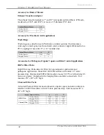
Catalog #
Ranges
For use with Hood
Shipping Wt. lbs. / kg.
9413400
100-115 volts, 50/60 Hz
Premier, XStream, XL
6 / 2.7
9413401*
208-230 volts, 50/60 Hz
Premier, XStream, XL
6 / 2.7
*International electrical configuration
**Modbus is a registered trademark of Schneider Automation
7117700 Cable, Airflow Monitor – Night Setback
This cable is pre-configured to attach to the three position switch at
minimum setting and send an input signal to the airflow monitor for
night setback to disable the air monitor and prevent it from
alarming. Use jumper wires 7115400 located in switch and control
box labeled 7110800 to prevent power being cut to the air monitor.
See wiring diagrams in Appendix C and item 17 in Appendix A.
Two Main Blower Modifications
There are two main ways to modify the performance of your blower as listed in
Chapter 3: Getting Started
. One way is the adjustment of the blower outlet
orientation. The other way is the adjustment of the fan speed to fine-tune the
performance of your blower/hood system. Refer to Chapter 3 for these
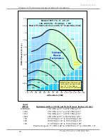
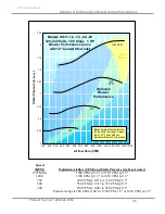
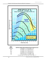
instructions. Additionally, all the performance data for your particular blower
model number are listed in
Chapter 4: Performance Data and Safety Precautions
.
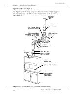
Additional Modifications by Adding Ductwork Accessories
There are additional ways to equip your blower by adding any of the accessories
on the following pages. To ensure that your blower exhaust system will operate
properly, the ductwork and accessories linking your hood and blower must be
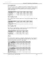
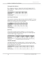
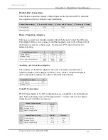
sized correctly. Along with the accessories listed next are the “equivalent
resistance in feet of straight duct” for each accessory. It is necessary to compute
the sum of the equivalent resistance factors for each accessory and ductwork
length for your entire hood/blower system. Then the blower can be sized properly
from the total equivalent resistance for your exhaust system. Blower Sizing
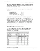
Example: You have selected a Labconco Protector Premier 48 Laboratory Hood at
100 fpm and 725 CFM. The static pressure of the Protector Premier 48 at 100 fpm
is 0.22". The exhaust collar of this hood is sized to receive 12" diameter PVC duct
directly. In this example, your fume removal system requires 30 feet of straight
Summary of Contents for 7061110
Page 36: ...Chapter 5 Using Your Blower Product Service 1 800 522 7658 32 Original instructions...
Page 48: ...Chapter 7 Modifying Your Blower Product Service 1 800 522 7658 44 Original instructions...
Page 58: ...Chapter 9 Troubleshooting Product Service 1 800 522 7658 54 Original instructions...
Page 62: ...Product Service 1 800 522 7658 58 APPENDIX B BLOWER DIMENSIONS...
Page 63: ...Appendix B Blower Dimensions Product Service 1 800 522 7658 59 Original instructions...
Page 64: ...Appendix B Blower Dimensions Product Service 1 800 522 7658 60 Original instructions...
Page 72: ...Product Service 1 800 522 7658 68 APPENDIX F TYPICAL PERCHLORIC ACID HOOD INSTALLATION DIAGRAM...

