background image


Logic+

®

 and Cell Logic+

®

 A2 | B2 Biosafety Cabinets 

Axiom

®

 C1 Biosafety Cabinets 

PuriCare

®

 Procedure Stations 


Register this product 

LABCONCO CORPORATION 

8811 Prospect Avenue 
Kansas City, MO 64132 
(800) 821-5525  I  +1 (816) 333-8811 

labconco.com 

Please read user’s manual before 

operating equipment 


Original Instructions 


Technical Manual 


Summary of Contents for Logic+ A2

Page 1: ...ety Cabinets PuriCare Procedure Stations Register this product LABCONCO CORPORATION 8811 Prospect Avenue Kansas City MO 64132 800 821 5525 I 1 816 333 8811 labconco com Please read user s manual befor...

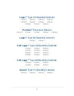
Page 2: ...31252xxx1 31262xxx1 Logic Type B2 Biosafety Cabinets 30348xxx1 30368xxx1 Cell Logic Type A2 Biosafety Cabinets 32239xxx1 33239xxx1 34239xxx1 32249xxx1 33249xxx1 34249xxx1 32259xxx1 33259xxx1 34259xxx...

Page 3: ...eplacement of all defective parts to restore the unit to operation Repairs may be completed by 3rd party service agents approved by Labconco Corporation Labconco Corporation reserves the rights to lim...

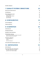
Page 4: ...S 15 Typographical Conventions 15 General Safety Precautions 17 Safety Precautions for this Product 19 3 CATALOG NUMBER CONFIGURATOR 21 4 SERIAL TAG 22 Serial Tag Location 22 Serial Tag Information 23...

Page 5: ...ION 40 Certifier Password 40 Adjusting Blower Speed 41 Adjusting the Internal Air Damper 43 Setting the Filter Life Gauge 45 Type A2 8 inch through 10 inch sash and Type B2 45 Type A2 12 inch sash and...

Page 6: ...HEPA Filter Leak Test Preparation 66 Theoretical Upstream Concentration 66 Upstream Concentration Sampling 66 Type C1 Supply HEPA Filter Leak Test 68 Acceptance Criteria 69 Type C1 Exhaust HEPA Filte...

Page 7: ...S 97 Tools 97 Required 97 Optional 97 Removal of External Dress Panels 98 Dress Panel 98 Side Panels 99 Front Sash 100 Sash Level Adjustment 100 Sash Sensor Adjustment or Replacement 101 HEPA Filter R...

Page 8: ...dule Components 141 Resetting a Circuit Breaker 142 Power Supply Board 143 Display Board 144 Speaker 145 Blower Motor 146 Wiring Diagrams 148 100 115V 148 208 240V 149 14 TROUBLESHOOTING 150 Blower an...

Page 9: ...KIT 165 Kit Catalog Numbers 166 Installation Procedure 166 Exhaust Damper Installation Procedure 167 Canopy Switch Wiring Connection 168 Calibrate for Operation 169 18 AIRFLOW SENSOR KIT 171 Installa...

Page 10: ...s to Towel Catch G4 Paper 188 Attach Prefilter s to Towel Catch Aluminum Washable 189 22 EN ALARM RELAY CONTACT KIT 190 Installation 190 Example 1 Blower Relay Contact Single Phase AC 194 Example 2 B...

Page 11: ...ns or need additional information please contact us Thank you for all your support in the past and in the future Contacting Labconco LABCONCO Corporation 8811 Prospect Avenue Kansas City MO 64132 USA...

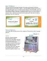
Page 12: ...t model specific information Below are examples of this color coded bar Theory of Operation This section offers a brief overview of the operation of Type A2 B2 and C1 biosafety cabinets Type A2 All Lo...

Page 13: ...ally safe designs with all contaminated areas under negative pressure Figure 1 3 All Logic Type C1 biosafety cabinets meet the airflow requirements of ANSI NSF Standard 49 Approximately 55 60 of the a...

Page 14: ...e Chem ZoneTM center work surface air is filtered and exhausted via a remote building exhaust system while the inflow and outer work surface air is filtered and recirculated All Type C1 Logic biosafet...

Page 15: ...renvoie une mise en garde d taill e dans ce manuel Typographical Conventions DANGER An imminently hazardous situation which if not avoided will result in death or serious injury DANGER Situation dang...

Page 16: ...r es voire graves PINCH POINT Areas or components that can pinch or cut Take care not to touch these defined areas POINT DE PINCEMENT Zones ou composants pr sentant un risque de pincement ou de coupur...

Page 17: ...s L absence de pr caution pour viter ces zones endommagera le produit TOOL REQUIRED Tool required to access specified area OUTIL N CESSAIRE Outil n cessaire pour acc der la zone sp cifi e General Saf...

Page 18: ...duit mauvais escient Ne jamais d sactiver annuler ou contourner les capots panneaux interrupteurs capteurs ou alarmes de s curit Ceci entra nerait des blessures graves la mort ou des dommages mat riel...

Page 19: ...garding certification agencies or need assistance in locating one contact Labconco s Product Service Department at 800 821 5525 or 816 333 8811 DO NOT load more than 150 lbs 68 kg in the work area Exc...

Page 20: ...ials to ultraviolet UV radiation Never bypass the UV safety interlock that only allows the UV light to work when the sash is closed When surface disinfecting the biosafety cabinet o Avoid splashing th...

Page 21: ...ovides key information about the model Use the configurator below to identify specifics about your product 30248xxx1 Product Group 3 Laminar Flow Products Product Family 0 Logic 1 PuriCare 2 4 Cell Lo...

Page 22: ...level under which the product was constructed It is the single most important piece of information when assistance is requested Serial Tag Location See Figure 4 1 for the location of the primary and...

Page 23: ...rmation is located on the Serial Tags Primary Serial Tag Serial Number Catalog Model Number Revision Electrical Requirements o Voltage o Frequency o Amperage o Phase Secondary Serial Tag Serial Number...

Page 24: ...ry installed Test Report Location The test report is located on the blower plenum cover which is behind the front dress panel See Figure 5 1 The Dress Panel Screws must be removed and the Dress Panel...

Page 25: ...located Important information is highlighted below Note The test report shown is an A2 12inch model with two internal blowers A2 12inch and C1 model reports list two blower speeds supply and exhaust...

Page 26: ...display a Data Plate on the front of the product in a readily visible location Data Plate Location See Figure 6 1 for the Data Plate location Dress Panel Primary Serial Tag Secondary Serial Tag Data...

Page 27: ...w Downflow Grid Test Point Locations Introduction Location for Test Aerosol Secondary Inflow Methodology NSF49 standard revision under which the biosafety cabinet is listed Figure 6 2 shows a Type A2...

Page 28: ...ust volumes and vacuum pressures required to properly operate each cabinet model are listed by cabinet width and sash operating height If a biosafety cabinet is being altered from recirculating operat...

Page 29: ...located on the top of the cabinet is designed to draw a maximum of 100 CFM 170 m3 hr Attempting to draw additional room air through the valve room air exhaust can result in unstable cabinet operation...

Page 30: ...xhaust airflow for each biosafety cabinet It also allows the biosafety cabinet to be sealed off from the building exhaust system should it become necessary to do so Note Type B2 models must always be...

Page 31: ...biosafety cabinets the recommended vacuum will remain constant throughout the life of the exhaust HEPA filter Duct vacuums below 0 05 inches H2O 12 Pa or above 0 5 inches H2O 125 Pa may result in err...

Page 32: ...ype B2 Models 1 WC Inches of Water Column typically expressed in units of inches H2O Logic Type B2 Model Airflow Volume Concurrent Balance Value Recommended Duct Vacuum ft3 min m3 hr ft3 min m3 hr WC1...

Page 33: ...t in erratic operation and throw an alarm condition from the product 2 WC Inches of Water Column typically expressed in units of inches H2O Axiom Type C1 Model Airflow Volume Concurrent Balance Value...

Page 34: ...t is important to understand the current configuration of the biosafety cabinet for many reasons some of which include Verify model and type Verify accessories installed Troubleshooting The Info Scree...

Page 35: ...2 inch and C1 Info AFS UV LIGHT CANOPY C1 A MODE REV D 10 INCH OK MUTE 58 CURRENT AVG 1217 1219 NEW FILTER MAX 1074 1800 REV D SUPPLY 51 CURRENT AVG 1103 1104 NEW FILTER MAX 994 1800 REV D EXHAUST UP...

Page 36: ...ncorrect operation of the biosafety cabinet and the biosafety cabinet may not protect the product personnel or environment Sash Height On Type A2 and B2 cabinets never change the sash height The follo...

Page 37: ...MUTE The first screen will display the biosafety cabinet type Do NOT change this selection press OK MUTE Type C1 CONFIGURATION CALIBRATION PASSWORD Password Entered TYPE A2 TYPE B2 TYPE C1 OK MUTE REC...

Page 38: ...Note When a Type C is selected previously the Canopy Screen will not appear but the software will default the selection correctly based on whether A mode No Canopy or B mode Canopy was previously sel...

Page 39: ...h the Type C1 will continue to operate while sounding an alarm when a remote building exhaust failure occurs This allows the user time to secure critical work and exit before the cabinet shuts off Set...

Page 40: ...or technician Changing parameters in the password protected area may impair the product s performance and result in loss of protection and or harm or death to personnel in the laboratory Certifier Pas...

Page 41: ...tifier To adjust the blower speed following these instructions 1 From the Main Menu press MENU using UP or DOWN select the Tools icon Press OK MUTE 2 Use UP or DOWN to select the Password icon press O...

Page 42: ...djust the blower speed Each single press of UP or DOWN increments the PWM signal sent to the blower by 0 5 It may take two presses of the button to see the displayed PWM value change however the blowe...

Page 43: ...ly downflow air and one to exhaust inflow air On these models the blower speed of each will be set electronically See the previous section Adjusting Blower Speed and note the text Supply displayed on...

Page 44: ...has 16 turns from fully open to fully closed The adjustment decal shows the number of turns from fully closed that balanced the biosafety cabinet correctly at the factory The adjustment bolt and adjus...

Page 45: ...ations or when the blower speed s have been adjusted slightly but the HEPA filters have not been replaced during an annual certification 3 Set Filter Life This option is seldom selected It may be used...

Page 46: ...ess OK MUTE Note On dual blower models each filter has a separate Life Gauge for percentage of filter remaining The lower of the two Filter Life percentages is displayed on the Home Screen 58 CURRENT...

Page 47: ...safety cabinet in the field which did not previously have this accessory installed first enable the Airflow Sensor in Configuration as described in Change Configuration in Section 8 Configuration To a...

Page 48: ...ge previously shown in this section until on the Filter Life Selection screen Then follow these instructions 1 On the Filter Life Selection screen press OK MUTE 2 Using the average inflow velocity mea...

Page 49: ...Sensor Value These values are not velocity or flow values they are the raw digital output values from the airflow sensor To avoid nuisance alarms in operation these two values should be at least 4 or...

Page 50: ...xhaust system stop all exhaust airflow before proceeding Once all airflow is removed press OK MUTE 2 The biosafety cabinet will display Wait for approximately 15 seconds while it samples the airflow s...

Page 51: ...ay need to be recalibrated if it has been determined the remote exhaust system is pulling the correct airflow volume To reach the VSS calibration screen access the Calibration submenu as described in...

Page 52: ...shown is Open adjust the VSS set screw slowly clockwise until the VSS status changes to Closed See Figure 9 4 for reference Then slowly turn the set screw counterclockwise until the status changes to...

Page 53: ...calibration screen a different password is required This password is LIGHT UV LIGHT TIMER OUTLET OK MUTE Type A2 HEPA Filter Leak Test Preparation All biosafety cabinet models were tested to the HEPA...

Page 54: ...on levels for the photometer using the actual values provided in Table 10 1 for the model being tested Upstream Concentration Sampling If the biosafety cabinet has NOT been used with biohazards toxic...

Page 55: ...600 1 23 12 4 foot 8 725 2 37 21 9 760 2 36 18 10 800 2 34 18 12 900 3 30 15 5 foot 8 900 2 30 17 9 950 2 28 14 10 1000 2 27 14 12 1130 3 24 13 6 foot 8 1100 2 25 17 9 1140 2 24 15 10 1200 2 23 15 12...

Page 56: ...ss Panel and LED lamps removed for clarity 3 Lower the front edge of the diffuser until it clears the bottom of the sash then pull the diffuser straight out of the biosafety cabinet See Figure 10 4 4...

Page 57: ...frame and the biosafety cabinet structure Note When scanning the front edge of the supply HEPA filter photometer operation may become erratic due to the aspiration of room air into the front of the w...

Page 58: ...the exhaust filter cover see Figure 10 7 Tilt the cover back to access the downstream side of the filter The exhaust HEPA filter media is now exposed Never touch the media it is easily damaged 2 The e...

Page 59: ...haust air stream This problem can be minimized or eliminated by placing the edge of a sheet of rigid plastic or metal just outside the edge of the HEPA filter when scanning the filter edges See Figure...

Page 60: ...o the photometer to establish the actual 100 concentration value the theoretical value will need to be used instead Testing at Labconco has shown the actual concentration varies from the theoretical v...

Page 61: ...culated Concentration ug L 1 Actual Concentration ug L 2 4 foot 8 445 1 30 15 6 foot 8 665 1 20 12 1 The calculated concentration was established using the formula Concentration ug l Laskin nozzles 23...

Page 62: ...s Panel and LED lamps removed for clarity 3 Lower the front edge of the diffuser until it clears the bottom of the sash then pull the diffuser straight out of the biosafety cabinet See Figure 10 12 4...

Page 63: ...e biosafety cabinet structure Note When scanning the front edge of the supply HEPA filter photometer operation may become erratic due to the aspiration of room air into the front of the work area This...

Page 64: ...Place the aerosol generator in the left rear corner of the biosafety cabinet s drip pan see Figure 10 15 Ensure that the generator is level and the oil level is within 1 8 inch 3 mm of the level line...

Page 65: ...s downstream of the exhaust HEPA filter and the same distance from any elbows in the duct work 2 Connect the sampling port to the photometer 3 Set the photometer sampling valve to DOWNSTREAM Ensure pr...

Page 66: ...tor is within 1 8 inch 3 mm of the level line 6 If the aerosol generator requires pressurized air connect the air line 7 Verify the generator s air pressure is 23 psi 8 Turn on the photometer and allo...

Page 67: ...et Width Sash Height inches Supply Air Displacement CFM Laskin Nozzles Required Calculated Concentration ug L 1 Actual Concentration ug L 2 4 foot 8 520 1 26 13 10 520 1 26 13 6 foot 8 665 1 20 12 10...

Page 68: ...s Panel and LED lamps removed for clarity 3 Lower the front edge of the diffuser until it clears the bottom of the sash then pull the diffuser straight out of the biosafety cabinet See Figure 10 19 4...

Page 69: ...rame and the biosafety cabinet structure Note When scanning the front edge of the supply HEPA filter photometer operation may become erratic due to the aspiration of room air into the front of the wor...

Page 70: ...an extension tube see Figure 10 22 on the aerosol generator to ensure the challenge aerosol is delivered to the center part of the rear baffle defined by the center drip tray the generator is resting...

Page 71: ...d Calculated Concentration ug L 1 Actual Concentration ug L 2 4 foot 8 283 1 48 28 10 354 1 38 22 6 foot 8 423 1 32 19 10 529 1 26 15 1 The calculated concentration was established using the formula C...

Page 72: ...Set the photometer sampling valve to DOWNSTREAM Ensure proper vacuum at the sampling tube 3 Open the appropriate number of Laskin nozzles on the aerosol generator see Table 10 5 4 Using a rigid tube...

Page 73: ...e concentration of aerosol downstream Acceptance Criteria Aerosol penetration shall not exceed 0 01 Reinstall the exhaust housing front plate unsecure temporary Inlet Relief Valve hold open reinstall...

Page 74: ...e glass sash The thermal anemometer probe should always point toward the nearest side wall or the sash whichever is closer to the probe Therefore on the two rear rows the probe should point to the lef...

Page 75: ...75 14 6 4 08 10 4 10 55 28 21 3 x 7 6 0 15 5 55 14 1 4 08 10 4 4 foot 8 9 55 28 24 3 x 8 6 0 15 5 75 14 6 5 21 13 2 10 55 28 24 3 x 8 6 0 15 5 55 14 1 5 21 13 2 12 60 30 24 3 x 8 6 0 15 5 44 13 8 5 21...

Page 76: ...sical permanent obstruction The Primary Method requires the following DIM Direct Inflow Meter such as a ShortridgeTM Labconco Holder Bracket Assembly Catalog Number 3836405 shown below in Figure 10 28...

Page 77: ...All air should enter through the DIM seal gaps around blocking plates completely 7 Turn on the DIM set it to read airflow volume continuously 8 Take 5 readings over a 1 minute period Average the resu...

Page 78: ...38 424 404 444 686 754 5 foot 8 105 3 36 0 31 353 336 370 571 629 9 105 3 78 0 35 397 378 416 642 707 10 105 4 20 0 39 441 420 462 714 785 12 105 5 05 0 47 530 505 555 858 943 6 foot 8 105 4 03 0 37...

Page 79: ...t identify the correct set of Sash Stops 1 right and 1 left Find the set of Second Generation Sash Stops which have a engraved under the width number For example if a 4 ft model is under test select t...

Page 80: ...mber of test points marked equals the width of the biosafety cabinet in feet For example a 5 ft width model should have 5 test points marked 6 Mark the 6th hole from the right side wall and subsequent...

Page 81: ...height required for this test Press OK MUTE to silence the alarm for 5 minutes 12 This test requires the anemometer to provide highly accurate results Establish the necessary correction factor to the...

Page 82: ...3 8 1 269 296 457 503 9 4 3 25 83 8 1 303 333 515 566 10 4 3 25 83 8 1 337 371 573 630 12 4 3 25 83 8 1 08 404 444 686 754 5 foot 8 5 3 25 83 10 1 336 370 571 629 9 5 3 25 83 10 1 378 416 642 707 10 5...

Page 83: ...hown in Table 10 8 18 If the Inflow Volume is not within the acceptance criteria range adjust the biosafety cabinet according to Adjusting the Blower Speed and or Adjusting the Internal Damper found i...

Page 84: ...r pickup at a height of 16 inches 41 cm above the work surface pointing up into the airflow Place the particle counter pickup at each of the three marked test points and take one sample at each test p...

Page 85: ...enterline c Continue marking additional test points along the centerline at 12 inch 30 5 cm increments until the left to right center of the work surface is reached d Repeat steps b and c starting fro...

Page 86: ...67 dbA when the biosafety cabinet is new and no more than 73 dbA when the filters are loaded with particulate Vibration Test optional The vibration level at the work surface should be measured as desc...

Page 87: ...surface 2 Place the radiometer probe at this point and with the biosafety cabinet s blower s light and UV light off take a background reading 3 Close the sash Turn on the biosafety cabinet s UV Light...

Page 88: ...outlets after the test the Reset Button on the right side outlet needs to be pressed 2 Press the test button on the GFCI tester The indicator lights on the tester should indicate the outlet is inacti...

Page 89: ...nflow inflow building exhaust system requirements HEPA filter specifications and leak test parameters The charts are provided in imperial English units only Much of the data is located in other areas...

Page 90: ...34 30 Actual aerosol conc ug l 4 14 12 12 21 18 18 15 Supply HEPA Data Labconco P N 3838400 3838400 3838400 3838401 3838401 3838401 3838401 Width x Depth x Height in 5 36x18x3 06 36x18x3 06 36x18x3 0...

Page 91: ...nc ug l 4 17 14 14 13 17 15 15 10 Supply HEPA Data Labconco P N 3838402 3838402 3838402 3838402 3838403 3838403 3838403 3838403 Width x Depth x Height in 5 60x18x3 06 60x18x3 06 60x18x3 06 60x18x3 06...

Page 92: ...width of the cabinet in feet i e 3 foot cabinet mark the first 3 points Repeat for the opposite side HEPA Filter Leak Test Specifications 3 Based on mineral oil 4 The actual aerosol concentration is...

Page 93: ...d 1 1 Theoretical aerosol conc ug l 3 30 15 Actual aerosol conc ug l 4 20 12 Supply HEPA Data Labconco P N 3838401 3838403 Width x Depth x Height in 5 48x18x3 06 72x18x3 06 Performance CFM 445 665 Pre...

Page 94: ...binet mark the first 4 points Repeat for the opposite side HEPA Filter Leak Test Specifications 3 Based on mineral oil 4 The actual aerosol concentration is what was observed during testing Aerosol ge...

Page 95: ...4 13 13 12 12 Supply HEPA Data Labconco P N 3838401 3838401 3838403 3838403 Width x Depth x Height in 5 48x18x3 06 48x18x3 06 72x18x3 06 72x18x3 06 Performance CFM 445 445 665 665 Pressure Drop in H2...

Page 96: ...for the opposite side HEPA Filter Leak Test Specifications 3 Based on mineral oil 4 The actual aerosol concentration is what was observed during testing Aerosol generator should be placed in the left...

Page 97: ...equired 2 Phillips screwdriver or 2 Phillips bit 4 inches long minimum Ratchet with extension Sockets o 5 16 inch o 3 8 inch o 7 16 inch o 1 2 inch 3 8 inch nut driver 1 2 inch nut driver Optional Cor...

Page 98: ...the dress panel out away from biosafety cabinet to clear the LED lamps underneath Then lift the entire dress panel up to clear the two white posts on the top right and left corners of the dress panel...

Page 99: ...ide panel needs to be removed position the panel so that it is almost closed Grasp the panel by the front and rear edges Lift the panel up approximately 2 inches 5 cm then pull it straight away from t...

Page 100: ...lateral play or movement Under normal operation the sash should remain level Occasionally during transport of the biosafety cabinet the sash may become unlevel Follow the instructions below to resolve...

Page 101: ...n examine the sash switches and adjust replace as necessary 1 Hinge open or remove the right end side panel as described earlier in this section under Removal of External Dress Panels 2 Locate the sas...

Page 102: ...s first click and within 2 inches 50 mm of upward travel a second click should be heard from the ALMOST CLOSED switch c OPERATING POSITION 1 continue raising the sash slowly from closed and when the b...

Page 103: ...ped silver tab 5 If a switch is not actuating properly move the sash so that the counterweight is well below the switch in question Move the silver tab on the switch with your finger If an audible cli...

Page 104: ...ter pan can be damaged if the plenum is raised with the exhaust HEPA filter in place HEPA filters can be awkward to handle and quite heavy for larger models Use safe lifting techniques when removing a...

Page 105: ...o the left or right and bend it slightly to free one end by getting it past the corner post Lift the blower plenum cover off Figure 12 8 Center Sash Support 6 Using a 1 2 inch socket loosen the 4 bolt...

Page 106: ...alling the supply HEPA filter to lower the plenum onto the supply HEPA turn the 3 plenum lift bolts counter clockwise Turn each bolt part way working in a pattern amongst the 3 bolts to lower the plen...

Page 107: ...er of the blower plenum cover Remove all screws except two along the top edge of the cover This will support the cover The sash stop bracket is held in place by two of the blower plenum cover screws R...

Page 108: ...catch and stop the filter from easily sliding out If this happens push the filter back in about 1 inch 25 mm pull the front edge of the filter down which will tilt the back edge up Maintain this filte...

Page 109: ...onto the supply HEPA turn the 3 plenum lift bolts counter clockwise Turn each bolt part way working in a pattern amongst the 3 bolts to lower the plenum evenly 2 When downward pressure begins to be ap...

Page 110: ...cabinet 3 Remove all of the Phillips screws around the perimeter of the exhaust filter cover Gently break the gasket seal on the cover by starting in one corner Use a flat screwdriver if necessary tak...

Page 111: ...blower plenum cover will rest on the center sash support Figure 12 18 after the final screws are removed Gently break the gasket seal on the cover by starting in one corner Use a flat screwdriver if n...

Page 112: ...lenum raises 1 2 inch 13 mm See Figure 12 19 for reference 9 Remove the 3 supply HEPA filter retainer brackets see Figure 12 20 11 Lift up on one corner of the supply HEPA filter to break the seal bet...

Page 113: ...g back and forth between the 2 bolts to lower the plenum evenly 2 When downward pressure begins to be applied onto the supply HEPA and upward pressure on the exhaust HEPA when it is reinstalled separa...

Page 114: ...cover by starting in one corner Use a flat screwdriver if necessary taking care not to damage the gasket or panel by prying too hard in one area Remove the exhaust filter cover See Figure 12 21 4 Usin...

Page 115: ...blower plenum cover will rest on the center sash support Figure 12 23 after the final screws are removed Gently break the gasket seal on the cover by starting in one corner Use a flat screwdriver if n...

Page 116: ...When reinstalling the supply HEPA filter to lower the plenum onto the supply HEPA turn the 3 plenum lift bolts counter clockwise Turn each bolt part way working in a pattern amongst the 3 bolts to low...

Page 117: ...replace the blower motor assembly never the motor or blower individually Failure to replace the blower motor with a genuine Labconco assembly will result in failed or incorrect operation which can jeo...

Page 118: ...e not to damage the gasket or panel by prying too hard in one area Once the gasket seal is free slide the cover to the left or right and bend it slightly to free one end by getting it past the corner...

Page 119: ...side of the connector The 16 pin data connector is released by depressing the single locking tab in the center of the connector on the side of the connector closest to the blower See Figure 12 29 9 U...

Page 120: ...cket into the plenum opening Make sure this rear blower bracket is INSIDE the plenum opening Once reinstalled and the three blower mounting bolts are installed and tightened verify the rear blower bra...

Page 121: ...replacing the blower motor Always wear gloves and eye protection when handling a blower motor assembly 1 Thoroughly and properly decontaminate the biosafety cabinet 2 Remove the front dress panel as...

Page 122: ...from the motor The 5 pin connector located closest to the blower is released by depressing the locking tabs on either side of the connector The 16 pin data connector is released by depressing the sing...

Page 123: ...e 12 34 9 Using a 1 2 inch socket or wrench remove the two upper and one lower mounting bolts See Figure 12 34 10 Grasp the motor and pull the assembly straight out of the biosafety cabinet See Figure...

Page 124: ...he motor or blower individually Failure to replace the blower motor with a genuine Labconco assembly will result in failed or incorrect operation which can jeopardize the protection the biosafety cabi...

Page 125: ...afety cabinet Note When sliding the exhaust HEPA filter out the rear edge of the filter frame may catch and stop the filter from easily sliding out If this happens push the filter back in about 1 inch...

Page 126: ...the connector on the side of the connector closest to the blower See Figure 12 38 Note On a Type C1 it may be difficult to reach the two motor wiring connectors described in Step 7 If this is the cas...

Page 127: ...free set that end of the exhaust plenum down gently then proceed to the two bolts on the opposite end Note 2x4 boards may be utilized to help support the exhaust plenum particularly on a Type C1 when...

Page 128: ...The blower motor assembly must be rotated approximately 45 degrees to orient it correctly for removal 11 The blower motor assembly must be rotated approximately 45 degrees to orient it correctly for r...

Page 129: ...ng Do NOT install fluorescent bulbs 1 Remove the dress panel as described in Removal of External Dress Panels 2 Locate the Left End Cap that aligns both LED lamps Figure 12 42 remove the Left End Cap...

Page 130: ...procedure Take care to look at both ends of the new LED Lamps One end is labeled with a and L N Figure 12 44 This end of the new LED Lamp must go to the right and is inserted into the Socket Cap 6 Wh...

Page 131: ...anging the LED the Lamps 4 To replace a socket cap insert a small straight bladed screwdriver into the socket near the lamp wire as shown in Figure 12 45 5 Once wires removed from the socket the socke...

Page 132: ...it 90 degrees and lifting it straight up and out of its sockets 6 Install new lamp by reversing the removal procedure 7 Reset the UV Hourmeter as follows In the Settings submenu enter UV Parameters th...

Page 133: ...ntaminate the UV lamp and the work area of the cabinet 4 Remove the UV lamp by rotating it 90 degrees then lift it straight up to free it from the sockets 5 Use a 1 Phillips screwdriver to remove the...

Page 134: ...ower When this prefilter becomes loaded with particulate replace it as follows Note The prefilter is not washable it must be replaced when dirty 1 Turn off the biosafety cabinet s blower 2 Following a...

Page 135: ...exhaust connected Type A2 will require the Ventus Canopy Connection Kit installed for the air tight damper to be installed above it To adjust airflow on a Labconco air tight damper follow these instr...

Page 136: ...rk surface and the grille into the work area for decontamination 6 Remove the front dress panel 7 Remove the sash stop bracket located near the top of the blower plenum cover 8 Lift the sash up until...

Page 137: ...standard models Using a large flat blade screwdriver and hammer remove the knockout by placing the screwdriver on the top or bottom of the plug strike the screwdriver with the hammer Repeat alternati...

Page 138: ...with the slot in the rear or bottom of the side panel The rear slot is located from 8 to 11 inches 222 to 288 mm from the bottom of the cabinet Note Make sure that the tube routing will not contact a...

Page 139: ...ing when properly seated 13 Tighten the 90 degree fitting compression nut hand tight and then using a 7 16 inch wrench tighten it at least turn more 14 Close the service valve in the cabinet and then...

Page 140: ...e the electronics module follow these instructions 1 Remove all power from the biosafety cabinet by unplugging the power cord 2 Using a 7 16 inch socket or nut driver remove the three nuts holding the...

Page 141: ...oard EN Alarm Dry Relay Contact optional and UV lamp ballast optional These components are identified in Figure 13 1 Figure 13 1 Outlet Circuit Breaker s Cabinet Circuit Breaker s Outlets Relay I O Bo...

Page 142: ...product and user should a device connected to an internal outlet experience an over current situation If the internal outlets do not have power when the Outlet icon is displayed on the Home Screen re...

Page 143: ...s an open frame dual output 5VDC and 12VDC voltage power supply If the power supply board is not operational or defective the LCD Display will not power on and the biosafety cabinet will not function...

Page 144: ...socket or nut driver remove the two nuts securing the display bracket See Figure 13 4 for reference The display board is attached to the display bracket and will come with the display bracket Remove t...

Page 145: ...e Figure 13 4 2 Using a putty knife or similar instrument dislodge the speaker from the biosafety cabinet s liner See Figure 13 6 for reference 3 If the adhesive holding the defective speaker to the l...

Page 146: ...y cabinet must have power supplied to it Take extra care when testing these wires to avoid electrical shock 1 The following wiring information lists each wire color as it enters the motor Since the mo...

Page 147: ...p 1 c above by the DC voltage measured in step 1 b above For example 13 7 volts measured across pins 1 10 PWM line and 23 7 volts measured across pins 1 15 13 7 23 7 0 58 This means the PWM signal is...

Page 148: ...148 Wiring Diagrams The wiring diagram is also located on the blower plenum cover behind the dress panel 100 115V...

Page 149: ...149 208 240V...

Page 150: ...150 14 Troubleshooting This section details common troubleshooting for the biosafety cabinet Blower and Lights not working...

Page 151: ...151 Blower only will not start...

Page 152: ...152 Lights only will not illuminate...

Page 153: ...153 UV Light will not illuminate...

Page 154: ...154 Airflow Alert activating...

Page 155: ...155 Filter Life Gauge not at 100 when new...

Page 156: ...156 Contamination in the work area...

Page 157: ...first option press OK MUTE to enter Sash Sensor diagnostics Note If the blower is on when entering the Sash Sensor Diagnostic screen it will automatically turn off 6 Slowly raise the sash from fully...

Page 158: ...tics option is highlighted then OK MUTE to select the submenu 5 Press DOWN to select the Keypad option press OK MUTE to enter Keypad diagnostics 6 Press and hold the keypad button to be tested When pr...

Page 159: ...menu 5 Press DOWN until the Airflow Sensor option is highlighted then OK MUTE to enter Airflow Sensor diagnostics 6 The display shows the status of the airflow sensor in the following order current se...

Page 160: ...opy diagnostic NOTE Type B2 cabinets will not display Canopy because they cannot have a canopy 6 The display shows the status of the Canopy Inlet Valve During normal operation it will be OPEN during a...

Page 161: ...e mini USB port on the side of the electronics module on top of the cabinet see Figure 16 1 The remotely connected computer can monitor the cabinet but not control the cabinet Connection Type To conne...

Page 162: ...ndard ASCII character set Note The mini USB port on the biosafety cabinet does not supply power it only transmits data Data Output Rate Status data is broadcast whether a recepient is receiving or not...

Page 163: ...finition The data string is limited to 80 characters including spaces and commas Use Figure 16 4 to understand the character signficance See Figure 16 5 on the following page for each character field...

Page 164: ...le software packages which can read RS232 type data and enter the data into a computer program such as a word processor to create a text file or spreadsheet to tabulate and plot the data Consult your...

Page 165: ...e is also referred to as the inlet relief valve The intake valve is angled such that the incoming make up room air must keep the valve open to maintain normal operation a loss of exhaust volume will a...

Page 166: ...installing the exhaust filter cover to prevent damaging the Exhaust HEPA filter 1 Turn off the Biosafety Cabinet Cabinet Width Feet Catalog Number 3 ft 3889200 4 ft 3889201 5 ft 3889202 6 ft 3889203...

Page 167: ...shown Line up the holes in the canopy connection with the threaded holes in the mounting bracket flanges Reference Figure 17 4 6 Install the four canopy bolts washers and lockwashers supplied with th...

Page 168: ...trol lever faces the front of the unit as shown in Figure 17 5 2 Use a proper silicone sealant not supplied and the screws supplied with the air tight damper to seal the damper to the canopy Canopy Sw...

Page 169: ...ion is highlighted then press OK MUTE to select the certifier s submenus 5 You will see a Warning Screen alerting you that you are about to enter an area that can alter the BSC s settings Press OK MUT...

Page 170: ...e cabinet for a canopy or not Use UP or DOWN to select Canopy After your selection is chosen press OK MUTE 12 This screen allows you to configure the cabinet s sash height Leave this setting alone and...

Page 171: ...r except the installation location is in the exhaust housing and the sensor wire pass thru is in the rear of the exhaust housing Exercise caution when working around the exhaust HEPA filter atop the b...

Page 172: ...side of the exhaust cover so that the screen end of the sensor body is oriented towards the front of the biosafety cabinet Reinstall the two screws removed in the previous step through the exhaust co...

Page 173: ...screws holding the sensor into its body See Figure 18 4 Do NOT pull the sensor out of the body 2 Install the bracket supplied with the kit onto the airflow sensor as shown in Figure 18 5 using the tw...

Page 174: ...ng grommet over the replacement plug noting the keyed orientation between the grommet and the plug See Figure 18 6 to identify the grommet and plugs described Note after becoming familiar with the sea...

Page 175: ...sensor to the biosafety cabinet s electronics module 1 Identify the Optional Airflow Sensor Input label on the left side of the biosafety cabinet s electronics module See Figure 18 8 2 Connect the ai...

Page 176: ...Password option is highlighted then press OK MUTE to select the certifier s submenus 5 You will see a Warning Screen alerting you that you are about to enter an area that can alter the BSC s settings...

Page 177: ...TE 10 This screen configures the unit for a UV light or not Leave this setting alone and press OK MUTE 11 This screen allows you to configure the cabinet for a canopy or not Leave this setting alone a...

Page 178: ...the Home Screen press MENU 2 Press DOWN until the Tools option is highlighted 3 Press OK MUTE to enter the menu screen 4 Press the DOWN button until the Password option is highlighted then press OK M...

Page 179: ...EM OR BLOCKING THE SENSOR INTAKE WITH TAPE 8 If the biosafety cabinet s internal blower was on it will automatically turn off Once all airflow from a remote building exhaust system has been removed if...

Page 180: ...P or DOWN to change the inflow as needed When the displayed value matches the value obtained during certification press OK MUTE 14 On type A2 C1 cabinets only calibrate the average downflow to match t...

Page 181: ...k surfaces before installing the UV Lamp 1 Disconnect all electrical power to the biosafety cabinet by unplugging the power cord 2 Using a 7 16 inch socket or nut driver remove the three acorn nuts th...

Page 182: ...COM common 3E BLK 7 Connect the UV ballast into the electronics module wiring harness as described below UV Ballast Wires White wire 2E WHT Black wire 25 ORG Red wires 16 RED 17 RED no orientation se...

Page 183: ...option is highlighted then press OK MUTE to select the certifier s submenus 5 You will see a Warning Screen alerting you that you are about to enter an area that can alter the BSC s settings Press OK...

Page 184: ...10 This screen configures the unit for a UV light or not Change the selection to UV Light press OK MUTE 11 This screen allows you to configure the cabinet for a canopy or not Leave this setting alone...

Page 185: ...re installing the UV Lamp 1 Disconnect power to the biosafety and raise the sash to the fully open position 2 Remove the four screws on the sidewalls and save them 3 Mount one of the IV brackets on ei...

Page 186: ...ile completing Step 5 5 Slide the other bracket onto the IV bar and fasten it to the opposite sidewall as done in Step 3 6 For the 5 ft and 6 ft IV Bars only fasten the center support brace onto the b...

Page 187: ...forward to disengage the rear tabs Support the underneath side with one hand while stabilizing the front edge with the other Set the work surface aside Reference Figure 21 1 2 Pinch and lift the work...

Page 188: ...1 Set the prefilter s item 1 in Figure 21 2 into the towel catch so they are located between the top and bottom long flanges on the towel catch See Figure 21 2 Figure 21 1 Work Surface Support Work Su...

Page 189: ...pring clips are used on 3 ft models Attach Prefilter s to Towel Catch Aluminum Washable 1 Set the prefilter s item 1 in Figure 21 2 into the towel catch so they are located between the top and bottom...

Page 190: ...ition To install the kit follow these instructions Installation A qualified electrician or certifier should install this kit 1 Disconnect all electrical power to the biosafety cabinet by unplugging th...

Page 191: ...22 4 on the opposite side of the board for use later 6 Install the Alarm Relay Contact board inside the electronics module using the screws standoffs lockwashers and nuts included with the kit First s...

Page 192: ...ct circuit board s J1 connector and the I O Transition board s J6 connector See Figure 22 5 for reference 8 Re secure the electronics module to the top of the biosafety cabinet If not utilizing the Re...

Page 193: ...ert the screwdriver rotate it up away from the wire and pull the wire straight out from the connector See Figure 22 6 for reference The relay contact closes when the condition is present on the biosaf...

Page 194: ...ll NOT start until the internal Airflow Sensor verifies proper exhaust airflow from the remote exhaust blower Once the blower successfully starts the contact will remain closed The generalized circuit...

Page 195: ...cessfully starts the contact will remain closed The generalized circuit shown below indicates how to interface the cabinet s provided contacts to power a Three Phase high current device like a remote...

Page 196: ...38401 Supply HEPA Filter 4 Foot Model 1 3838402 Supply HEPA Filter 5 Foot Model 1 3838403 Supply HEPA Filter 6 Foot Model 3 2 1297503 Lamp LED 3 Foot Model 2 1297504 Lamp LED 4 Foot Model 2 1297505 La...

Page 197: ...A Filter 4 Foot B2 Model 1 3438503 Exhaust HEPA Filter 6 Foot B2 Model 2 1 3838401 Supply HEPA Filter 4 Foot Model 1 3838403 Supply HEPA Filter 6 Foot Model 3 2 1297504 Lamp LED 4 Foot Model 2 1297506...

Page 198: ...EPA Filter 4 Foot Model 1 3838503 Exhaust HEPA Filter 6 Foot Model 2 1 3838401 Supply HEPA Filter 4 Foot Model 1 3838403 Supply HEPA Filter 6 Foot Model 3 2 1297504 Lamp LED 4 Foot Model 2 1297506 Lam...

Page 199: ...odels 3436816 Air Foil Grille 6ft A2 12 Sash models 5 3401300 Towel Catch 3ft 3401301 Towel Catch 4ft 3401302 Towel Catch 5ft 3401303 Towel Catch 6ft 6 3328600 Display PCB 7 3329700 Speaker 8 1233000...

Page 200: ...200 Figure 23 4 1 2 4 3 5 7 6 8 8...

Page 201: ...201 END OF 3849920 Figure 23 5 9 10 11 12 13...

Reviews: