49
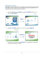
3. The nominal set point for Inflow has been set in the previous step. Now the
alarm set point must be established. The screen below is displayed. While on
this screen, reduce the remote or building exhaust system until the
TOTAL
volume of air drawn by the remote exhaust system is reduced to 90% of nominal.
For a B2 biosafety cabinet, the remote exhaust system pulls both the downflow
air volume AND inflow air volume from the cabinet and exhausts it.
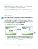
4. Once the total exhaust airflow has been reduced to 90% of nominal, look at the
Current Sensor Value
. It should be at least 4 or 5 points less than the
Nominal
Sensor Value
. These values are not velocity or flow values, they are the raw
digital output values from the airflow sensor. To avoid nuisance alarms in
operation, these two values should be at least 4 or 5 points apart. Press
[OK/MUTE]
.
5. Restore the remote exhaust system to nominal airflow. Press
[OK/MUTE]
.
REDUCE EXHAUST FLOW
TO 90%, PRESS OK
AIR SENSOR: 219
ZERO / NOMINAL: 95 / 220
Logic+ Type B2 Model
Inflow @ 90%
Alarm Set Point
ft
3
/min
m
3
/hr
4-foot, 8" Sash
216
367
6-foot, 8" Sash
322
547
Note:
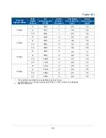
To set alarm point airflow,
i
f unable to
measure airflow in the exhaust duct above the
biosafety cabinet, slowly close the Air-Tight
Damper until the Inflow into the cabinet equals
the values in Table 9-1.
Table 9-1
Nominal
Sensor
Value
Current
Sensor
Value
RESTORE EXHAUST FLOW
TO 100%, PRESS OK
AIR SENSOR: 219
ZERO / NOMINAL: 95 / 220
Summary of Contents for Logic+ A2
Page 149: ...149 208 240V...
Page 151: ...151 Blower only will not start...
Page 152: ...152 Lights only will not illuminate...
Page 153: ...153 UV Light will not illuminate...
Page 154: ...154 Airflow Alert activating...
Page 155: ...155 Filter Life Gauge not at 100 when new...
Page 156: ...156 Contamination in the work area...
Page 200: ...200 Figure 23 4 1 2 4 3 5 7 6 8 8...
Page 201: ...201 END OF 3849920 Figure 23 5 9 10 11 12 13...


