79
Secondary Method
NSF/ANSI Standard 49 now requires the Primary Method for determining inflow be
utilized unless there is less than 41 inches (104 cm) clearance between the front of the
biosafety cabinet and the nearest physical, permanent obstruction. If there is less than
41 inches (104 cm) between the front of the biosafety cabinet and the nearest physical,
permanent obstruction, the Secondary Method for measuring inflow may be used.
The Secondary Method requires the following:
Thermal Anemometer
Labconco Certifier Kit (Catalog Number 3858400), which contains:
o
Labconco Holder Bracket Assembly (Catalog Number 3836405)
o
Left and Right Sash Stops, to position sash at correct restricted height
3-ft through 6-ft (Logic Generation)
3-ft through 6-ft (Logic+ Generation)
1. Based on the width of biosafety cabinet under test, identify the correct set of
Sash Stops (1 right and 1 left). Find the set of Second Generation Sash Stops,
which have a ‘+’ engraved under the width number. For example, if a 4-ft model
is under test, select the two Sash Stops engraved with a ‘4 +’.
2. Place the thermal anemometer probe into the Labconco Holder Bracket
Assembly. For convenience, the 6-ft Sash Stops have two lines to position the tip
of the thermal anemometer correctly in the Holder. The thermal anemometer
should be positioned such that the distance from the bottom of the Holder
Bracket to the center of the anemometer element equals the value in column
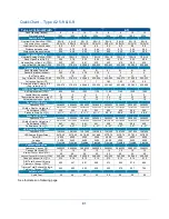
“Probe Distance” in Table 10-8 based on model width. 3-ft and 6-ft model widths
require the 3.25 inch (83 mm) position; 4-ft and 5-ft model widths require the 4.00
inch (102 mm) position. See Figures 10-29 (Sash Stop) and 10-30 (direct
measurement with a ruler) below. Tighten thumbnuts on Holder to secure probe.
Figure 10-29
Figure 10-30
Anemometer
Element Center
6-ft Sash
Stop
Labconco
Holder
(3836405)
Ruler
m
e
a
s
u
re
Summary of Contents for Logic+ A2
Page 149: ...149 208 240V...
Page 151: ...151 Blower only will not start...
Page 152: ...152 Lights only will not illuminate...
Page 153: ...153 UV Light will not illuminate...
Page 154: ...154 Airflow Alert activating...
Page 155: ...155 Filter Life Gauge not at 100 when new...
Page 156: ...156 Contamination in the work area...
Page 200: ...200 Figure 23 4 1 2 4 3 5 7 6 8 8...
Page 201: ...201 END OF 3849920 Figure 23 5 9 10 11 12 13...


