94
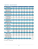
Type B2 Footnotes
Type and Model Identification
The primary serial tag is on the lower right edge of the front dress panel.
The secondary serial tag is on the front of the electronics module on the
cabinet’s top right side.
The first two digits of the serial number are the year of production; the next two are the month. The next 5
digits are the sequence of production, and the letter following the serial number is the revision level of the
cabinet.
See
Section 3:Catalog Number Configurator
to discern Type, Model, and Sash Height from Catalog Number
found on the serial tag.
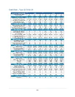
Downflow Test Specifications
All models are classified as uniform downflow.
All tests performed as described in the current NSF/ANSI Standard 49.
UV Lamp, IV bar and all other accessories must be removed before measuring downflow.
Inflow Test Specifications
All tests performed as described in the current NSF/ANSI Standard 49.
Secondary Inflow Test Specifications
Must use Labconco holder P/N 3836405 to perform this test properly.
1. Use the appropriate template included in Certifier Kit# 3858400.
2. Measured from bottom edge of the probe holder to center of the thermal anemometer element.
Locate the single row of holes at the front of the grille. Mark the 6
th
hole from the side wall and subsequent
test points every 9 holes until the number of test points marked equals the width of the cabinet in feet (i.e. 4-
foot cabinet, mark the first 4 points). Repeat for the opposite side.
HEPA Filter Leak Test Specifications
3. Based on mineral oil.
4. The actual aerosol concentration is what was observed during testing.
Aerosol generator should be placed in the left rear corner of the work area, pointing at the rear grille.
For uncontaminated units, the upstream concentration for the Supply HEPA only can be sampled from the
tube located under the work surface.
Supply and Exhaust HEPA Filter Specifications
5. Without gasket
Motor / Blower Specifications
Each motor must be programmed by Labconco for the appropriate width cabinet. The PWM setting will
fluctuate depending on local temperature and pressure.
LED Lamp Specifications
7. THIS PRODUCT USES DIRECT DRIVE T8 LED LAMPS INSTEAD OF FLUORESCENT LAMPS. THERE
IS NO BALLAST; LINE VOLTAGE IS SUPPLIED TO THE LAMP SOCKETS. DO NOT INSTALL
FLUORESCENT LAMPS! FOR REPLACEMENT LED LAMPS, CONTACT LABCONCO PRODUCT
SERVICE DEPARTMENT.
Remote Exhaust System Data
8. DIM = Direct Inflow Meter
9. Total Exhaust Volume required from remote (building) exhaust system.
10. Measured as per ASHRAE methodology for measuring air volume in round ducts. These values are
approximations, as the calculated traverse volume value may vary depending on sampling location, exhaust
system, and methodology.
11. Measured at the exhaust transition sampling point, relative to atmosphere.
UV lamp Specifications
For all models, the UV lamp model is G30T8. Labconco p/n is 1271300.
For all 115/230 VAC models, the ballast assembly is Labconco p/n 3829901.
For all 100 VAC models, the ballast assembly is Labconco p/n 3830600.
Summary of Contents for Logic+ A2
Page 149: ...149 208 240V...
Page 151: ...151 Blower only will not start...
Page 152: ...152 Lights only will not illuminate...
Page 153: ...153 UV Light will not illuminate...
Page 154: ...154 Airflow Alert activating...
Page 155: ...155 Filter Life Gauge not at 100 when new...
Page 156: ...156 Contamination in the work area...
Page 200: ...200 Figure 23 4 1 2 4 3 5 7 6 8 8...
Page 201: ...201 END OF 3849920 Figure 23 5 9 10 11 12 13...


