171
18: Airflow Sensor Kit
To add an airflow sensor (Catalog Number 3405500) to a Type A2 or C1 biosafety
cabinet, follow these instructions. If replacing an airflow sensor, it is not necessary to
configure the airflow sensor, as the biosafety cabinet will already have this feature
enabled.
Note:
These instructions describe installation on a Type A2 biosafety cabinet.
Installation on a Type C1 is very similar, except the installation location is in the exhaust
housing, and the sensor wire pass-thru is in the rear of the exhaust housing.
Exercise caution when working around the exhaust HEPA filter atop the biosafety
cabinet. The filter media can be damaged easily. Never touch the filter media.
Installation
– Type A2 without Ventus Canopy
1. Disconnect all power from the biosafety cabinet by unplugging the power cord.
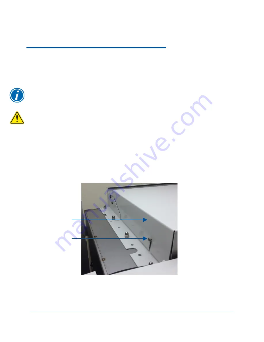
2. Loosen the two Phillips screws on the front sides of the exhaust cover. See
Figure 18-1.
3. Tilt the exhaust cover up to access the underside of the cover.
Figure 18-1
Phillips screw
Exhaust cover
Summary of Contents for Logic+ A2
Page 149: ...149 208 240V...
Page 151: ...151 Blower only will not start...
Page 152: ...152 Lights only will not illuminate...
Page 153: ...153 UV Light will not illuminate...
Page 154: ...154 Airflow Alert activating...
Page 155: ...155 Filter Life Gauge not at 100 when new...
Page 156: ...156 Contamination in the work area...
Page 200: ...200 Figure 23 4 1 2 4 3 5 7 6 8 8...
Page 201: ...201 END OF 3849920 Figure 23 5 9 10 11 12 13...


