102
Figure
D-16
Figure D-17
Figure D-18
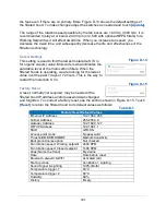
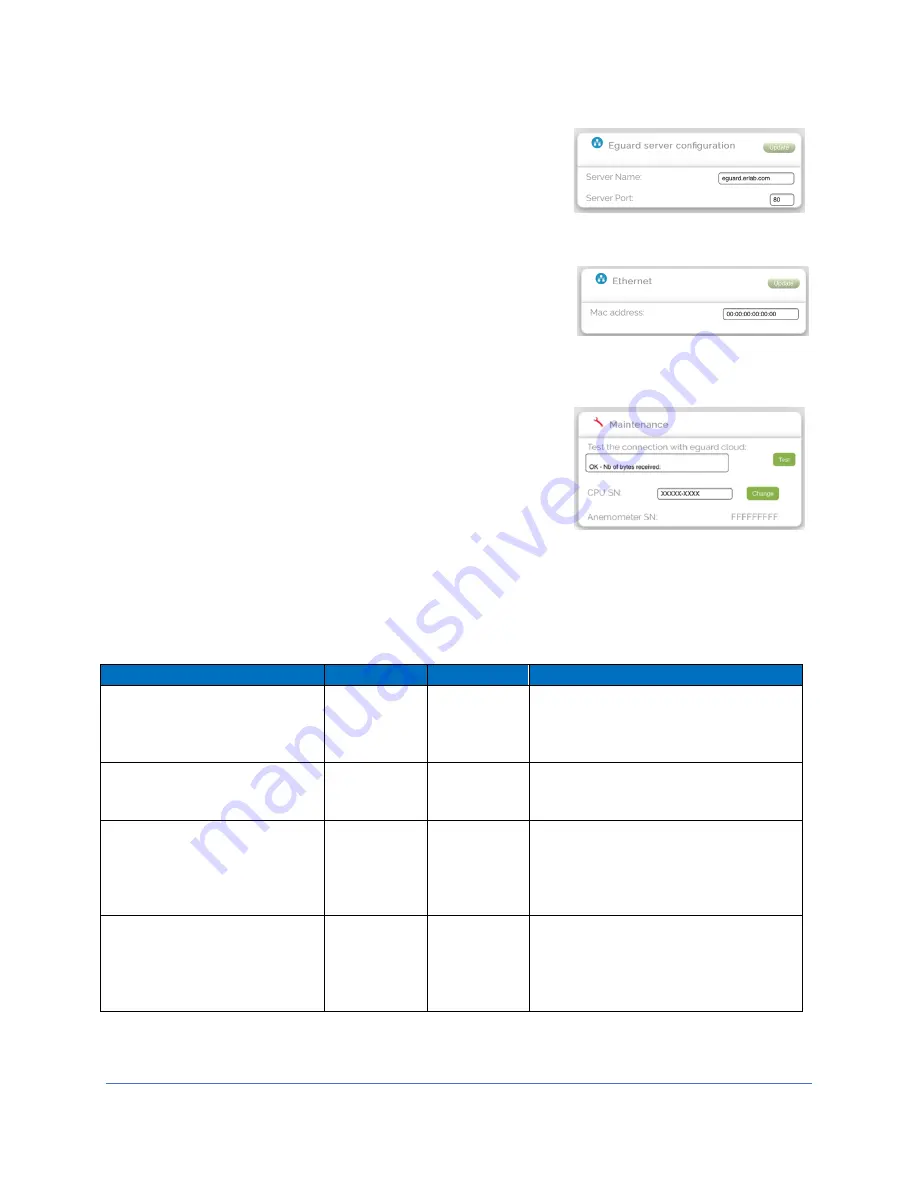
eGuard Server configuration
The eGuard server can be changed. Shown in Figure D-
16 is the default. If changes are needed, simply type the
desired server settings in the boxes. To make changes
touch
[Update]
. The same can be done for the server
port.
Ethernet
Ethernet settings can be modified here. Shown is the
default, but adjustment is possible. To make changes
touch
[Update]
.
Maintenance
Test to see the connection with eGuard cloud. The
display provides the test results after touching
[Test]
. It
is also possible to change the CPU SN. If you want the
computer serial numbers to be different (for example,
easier to remember, similar to other filtered hoods,
easier to identify, coincide with room number hood is in,
etc.) type in what you want and touch
[Change]
for it be
affective. The anemometer is not possible to change but
is shown for reference.
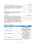
eGuard Access Summary
Address
Username Password
Description
192.168.1.1/
index
.html
*
*
Displays operation summary and
alarm messages.
Shows internal time, temperature
and relative humidity values.
192.168.1.1/
log
.html
*
*
Records of use and events that
occur for the filtered hood. Can be
exported.
192.168.1.1/
settings
.html
gfh
2018
Includes options to change:
Names, Time/Date, hood
connection, Start up, Sensor
Sensitivity, Temperature, Volume
& Brightness
192.168.1.1/
update
.html
ach
ach
Includes options to change:
Fan Speeds, Sensor Settings,
Factory Reset, Server
Configuration, Ethernet Options,
Connection Test
*Index and Log do not require a username or password.
Table D-2
Summary of Contents for Protector Airo
Page 78: ...78 Fans and Lights not working ...
Page 79: ...79 Vertical sash no longer operates smoothly ...
Page 80: ...80 Electrical duplex outlets no longer have power Fan operates but lights dim or not working ...
Page 81: ...81 Contaminates outside the filtered hood ...
Page 82: ...82 Lights operate but fans will not ...
Page 83: ...83 Smart Command Alarms ...
Page 84: ...84 If needed contact Labconco to troubleshoot further ...
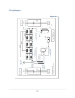
Page 94: ...94 Wiring Diagram Figure C 1 ...


