53
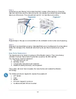
#10 SELF-THREADING SCREW
#10 KEPS NUT
Step 4
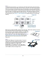
To access the base frames, you must remove the filters and fan box above the frame,
as well as the base frames, filters and fan boxes to the left of the frame being replaced.
This occurs because the base frames have an interlocking connection system to limit
the amount of wiring needed. The base frames are stacked such that the far right frame
cannot be taken out without first removing all others. Also before removing any filters,
make sure they are labeled with the column they are in, and that the filters have a P or
S. For reference, see
Section 4: Filter Installation
for detailed direction on technology
labeling.
Make sure to handle the filters and fan boxes with care. Stack them near but out of the
way of the filtered hood for safe keeping. Also remember
the base frame is what holds the pre-filter, so handle with
care and either dispose of them (and replace later) or
store at this time. For pre-filter replacement see
Replacement previously in this section
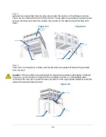
. What remains
after the removal is only the base frames as shown in
Figure 8-9.
Step 5
Remove and dispose of the base frames. To do this,
use the 5/16-inch hex nut driver and cordless drill to
remove the two screws at the rear and two nuts at
the front. See Figure 8-10. SAVE THIS
HARDWARE. The hardware of every base frame
being removed must be taken out and kept track of.
This hardware will be used again soon.
IF THIS FRAME NEEDS TO BE
REPLACED, THE COLUMN ON
TOP & ALL COLUMNS TO THE
LEFT NEED TO BE REMOVED
INTERLOCKING
CONNECTION
COLUMN ON TOP
COLUMN TO
THE LEFT
COLUMN TO
THE LEFT
BASE
FRAME
PRIMARY
FILTER
SECONDARY
FILTER
Figure 8-10
Figure 8-9
Figure 8-8
Summary of Contents for Protector Airo
Page 78: ...78 Fans and Lights not working ...
Page 79: ...79 Vertical sash no longer operates smoothly ...
Page 80: ...80 Electrical duplex outlets no longer have power Fan operates but lights dim or not working ...
Page 81: ...81 Contaminates outside the filtered hood ...
Page 82: ...82 Lights operate but fans will not ...
Page 83: ...83 Smart Command Alarms ...
Page 84: ...84 If needed contact Labconco to troubleshoot further ...
Page 94: ...94 Wiring Diagram Figure C 1 ...


