32
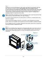
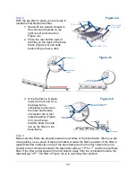
4. Place the cap from step 5 (Figure 4-3) on the connector called out in Figure 4-
8
(titled “Place cap here”). This is important to protect the filter junction for
future use. Do not skip this step.
Step 15
Make sure the secondary filter is properly seated on all sides of the fan box. When all
secondary filters are in place, use a piece of tape and marker to
label the filter’s
position. If the filter is placed in the first column (the one closest to the command
module) the tape label will sa
y “1S” for 1
st
column and secondary filter. If the filter is
above the fan in the 3rd column away from the
command module, label it “3S”.
Step 16
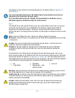
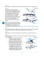
Repeat steps 14 & 15 with all the secondary filters needed for your size of filtered hood.
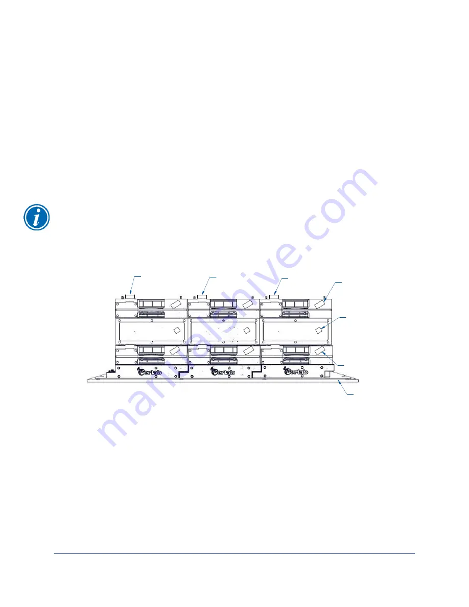
For a 5FT (M3) filtered hood example of what the completed filter installation looks like
including column labels see Figure 4-9. Your filtered hood should be stacked and
labeled like Figure 4-9. Caps should be on
top of all the secondary filter’s connections to
protect them. The command module side is called out for reference.
Calibrating the Airflow Sensor
Airflow sensor calibration is required for safe operation of the filtered hood. The
calibration is important for the function of the filtered hood and should be repeated
frequently. An annual calibration is recommended to ensure accuracy while in use. The
entire process will take about 5 minutes to complete. Always make sure no wiring,
plumbing or power cords are blocking the inlet of the sensor.
Always calibrate with
both side panels installed to prevent cross drafts near the airflow sensor.
Step 1
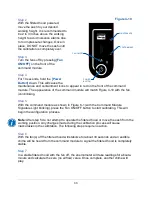
Turn the filtered hood on. The lights and fans should be working properly with no errors.
1 P
2 P
3 P
1 S
2 S
3 S
1
2
3
CAP
CAP
CAP
"1S" LABEL
"1" LABEL
"1P" LABEL
SIDE OF THE
COMMAND MODULE
Figure 4-9
Summary of Contents for Protector Airo
Page 78: ...78 Fans and Lights not working ...
Page 79: ...79 Vertical sash no longer operates smoothly ...
Page 80: ...80 Electrical duplex outlets no longer have power Fan operates but lights dim or not working ...
Page 81: ...81 Contaminates outside the filtered hood ...
Page 82: ...82 Lights operate but fans will not ...
Page 83: ...83 Smart Command Alarms ...
Page 84: ...84 If needed contact Labconco to troubleshoot further ...
Page 94: ...94 Wiring Diagram Figure C 1 ...

