background image

Chapter 3: Getting Started


Product Service 1-800-522-7658 

12


Work Surface Specifications 

The work surface should be smooth, rigid, and durable, such as a chemically 
resistant epoxy resin or stainless steel.  The surface should be non-porous and 
resistant to the acids, solvents and chemicals used in conjunction with the 
XPert or XVS enclosure.  The work surface should also contain a dished 
recessed area for containing primary spills. 

Work Surface and Vented Enclosure Installation 

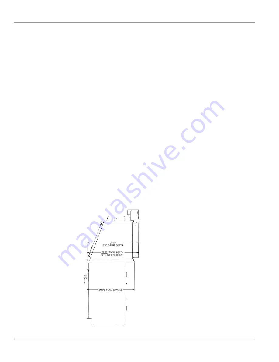
1.  Level the base cabinets and the work surface.  Work surface should be 

placed flush with the front of the base cabinet as shown in Figure 3-1. 

2.  Position the work surface in its intended location and with the front of 

the work surface, (wide flange or spill trough), towards you. 

3.  Secure the work surface to the base cabinet with a structural adhesive 

or silicone sealant. 

4.  Insert the supplied mounting screws in the four holes for epoxy work 

surfaces.  For stainless steel work surfaces use #10-24 x 3/8" hex 
machine screws. (Labconco P/N 1885806).  Allow a minimum of 1/8" 
clearance under the head of the screw for positioning the enclosure. 

5.  Place the enclosure on the work surface and slide the rear flange and 

front air foil flanges under the mounting screw heads. 

6.  Tighten the four screws to complete the installation. 


Figure 3-1 

Side View of Typical Installation 

Summary of Contents for Protector XVS Series

Page 1: ...971662 3971671 3971672 3971800 3971801 3971802 3971821 3971822 3971830 3971831 3971832 3971841 3971842 8 3971860 3971861 3971862 3971871 3971872 XVS Ventilation Stations 4862010 4862011 4862012 486202...

Page 2: ...00 a m and 6 00 p m Central Standard Time Part 3901000 Rev D ECO E117 Warranty Labconco provides a warranty on all parts and factory workmanship The warranty includes areas of defective material and w...

Page 3: ...erMate Portable Exhausters 8 Electrical Requirements 9 Space Requirements 9 CHAPTER 3 GETTING STARTED 10 Unpacking Your Vented Enclosure 11 Installing the Vented Enclosure on a Supporting Structure Wo...

Page 4: ...ion 34 Guardian Digital 1000 Installation Procedure 34 Digital 1000 Calibration 36 CHAPTER 7 ACCESSORIZING YOUR ENCLOSURE 38 Work Surfaces 40 Guardian Digital Airflow Monitor or Guardian Jr 40 Fluores...

Page 5: ...n Station has been engineered to provide maximum containment It will effectively contain toxic noxious or other harmful materials when properly installed The XPert or XVS offers many unique features t...

Page 6: ...e or other apparatus Additionally a balance should be strategically placed in the lab to provide efficient workflow Carefully read this chapter to learn the requirements for your installation site The...

Page 7: ...um requirement A bench that is rigidly mounted to the floor or fixed to the wall but not both may be appropriate The corners of a building typically have less vibration than the center The bench with...

Page 8: ...surfaces within the balance enclosure Containment of harmful powders prevention of cross contamination and clean up is all enhanced when static attraction of powders is minimized The construction of t...

Page 9: ...enon materials can also be classified by their surface resistivity measured in ohms per square The table below lists the surface resistivity of various classes of material Surface Resistivity Table Ma...

Page 10: ...ion Adapter 3912400 which is sold with the FilterMate Multiple FilterMate Portable Exhausters require the airflow to be properly balanced The 5 6 and 8 enclosures require two or three FilterMate Porta...

Page 11: ...s 35 16 7053501 Explosion Proof Remote Blower 115 volts 60 Hz 4 4 amps 40 18 B 1 4 hp or 1 3 hp belt drive with adjustable sheave to change RPM Corrosion resistant epoxy coated steel housing and wheel...

Page 12: ...rbon 280 None 3970002 115 Volt 60 Hz HEPA 280 Canopy to outside 3970003 115 Volt 60 Hz HEPA Carbon 220 None 3970004 115 Volt 60 Hz Carbon Carbon 220 None 3970020 230 Volt 50 Hz HEPA 280 None 3970021 2...

Page 13: ...r be connected directly to the auxiliary switched outlet on the rear of the FilterMate so the airflow monitor is ON when the blower is ON The FilterMate auxiliary switched outlet is rated for 8 amps F...

Page 14: ...ly Seal the enclosure to the work surface Arrange validation for the enclosure Depending upon which model you are installing you may need common plumbing and electrical installation tools in addition...

Page 15: ...Do not discard the packing material until you have checked all of the components and tested the unit We recommend that you do not remove the enclosure from its shipping container until it is ready to...

Page 16: ...he front of the base cabinet as shown in Figure 3 1 2 Position the work surface in its intended location and with the front of the work surface wide flange or spill trough towards you 3 Secure the wor...

Page 17: ...accessory transition adapters Labconco manufactures transition adapters for either top or bottom exhaust and for both 5 dia hose or 6 dia duct Review Chapter 2 for remote blower and FilterMate Portab...

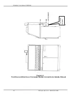
Page 18: ...Chapter 3 Getting Started Product Service 1 800 522 7658 14 Figure 3 3 Front View and Side View of Concealed Bottom Connection to Outside Exhaust To Outside Exhaust...

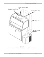
Page 19: ...1 800 522 7658 15 Figure 3 4 Top Connection to FilterMate Portable Exhauster Exhausted to Room Accessory Fluorescent Light Exhaust Transition Adapter Accessory Airflow Monitor 5 ID Hose included with...

Page 20: ...apter 3 Getting Started Product Service 1 800 522 7658 16 Figure 3 5 Concealed Bottom Connection to FilterMate With Outside Thimble Exhaust Connection To Outside Exhaust Via Thimble Connection 6 nomin...

Page 21: ...l See Appendix D The average face velocity is achieved by taking readings in two rows across the enclosure with the readings 6 from the ends and evenly spaced every 12 the first row is 3 down from the...

Page 22: ...ctively contain toxic noxious or other harmful materials when properly installed and operated What makes the XPert XVS Enclosure so unique is the revolutionary way it directs air into and through the...

Page 23: ...Chapter 4 Performance Features and Safety Precautions Product Service 1 800 522 7658 19 12 13 8 10 16 7 5 9 1 14 4 3 6 2 5 Figure 4 1...

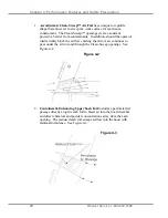
Page 24: ...In addition should the operator inadvertently block the airflow entering the airfoil air continues to pass under the air foil and through the Clean Sweep openings See Figure 4 2 2 Containment Enhancin...

Page 25: ...lution air supply reduces stagnant pockets of air in the upper interior See Figure 4 4 4 Zoned Rear Perforated Baffle directs horizontal laminar air streams to the three zoned sections of the perforat...

Page 26: ...rn balances and other auxiliary equipment without extending outside the enclosure or resting on the lower air foil 8 Two Enclosure Heights and Depths available as standard enclosures in 22 75 or 32 Ta...

Page 27: ...aust transition connectors are reviewed in Chapters 2 and 3 and accessories displayed for order in Chapter 7 13 Accessory Guardian Airflow Monitor or Guardian Jr Monitor continuously monitors airflow...

Page 28: ...will change the airflow pattern in the enclosure causing turbulence Do not store containers or supplies against the rear baffle as this will affect airflow Always work with your hands as far back in t...

Page 29: ...Only raise the sash for loading Check the baffle air slots for obstructions Allow the enclosure to operate unobstructed for 1 minute Wear a long sleeved lab coat and rubber gloves Use protective eyewe...

Page 30: ...flow patterns of the enclosure Final Purging Upon completion of work the enclosure should be allowed to operate for two to three minutes undisturbed to purge airborne contaminants from the work area b...

Page 31: ...derstanding of how to work in the enclosure we will review the suggested maintenance schedule and the common service operations necessary to maintain your enclosure for peak performance Only trained a...

Page 32: ...rear baffle should be checked for any blockage to ensure that the enclosure is maintaining proper airflow All weekly activities Annually Replace the fluorescent lamps on accessory light kit Have the...

Page 33: ...ow conditions 3 Alarm Indicator This red light is activated approximately 6 seconds after the low flow set point is reached 4 Test Reset Button If no alarm is present this button will cause the red la...

Page 34: ...the tube stem into the 0 50 hole on the enclosure Silicone sealant may be applied between the tube stem and the enclosure 7 Route the clear plastic tubing without kinks between the rubber elbow tubing...

Page 35: ...522 7658 31 Hardware nuts that attach to the hardware stud below Small 0 50 Dia Hole Plug Figure 6 2 Hole Plug Location Mounting Screws Figure 6 3 Guardian Jr Details Airflow Monitor Rubber Elbow Clea...

Page 36: ...m conditions are set at face velocities of 10 to 20 feet per minute below the normal operating conditions due to supply air and exhaust air fluctuations as well as room air cross drafts 5 Using a prop...

Page 37: ...losure Product Service 1 800 522 7658 33 Enclosure Operating In Flow Speed Alarm Condition Set Point Speed 100 fpm 80 90 fpm 80 fpm 60 70 fpm 60 fpm 40 50 fpm Enclosure Accessory Light Airflow Monitor...

Page 38: ...program the monitor There is also a green LED SAFE yellow LED CAUTION and red LED LOW with audible alarm for airflow conditions The audible alarm can be permanently muted if desired The Guardian Digit...

Page 39: ...flow monitor Plug the 115V power supply into a standard 115V duplex receptacle the back of the accessory FilterMate portable exhauster or the back of the accessory light For 230V plug an adapter or ad...

Page 40: ...Point Enclosure Operating In flow Speed Low Calibration Set Point High Calibration Set Point 40 50 fpm 60 fpm 40 60 fpm 100 120 fpm 60 70 fpm 80 fpm 50 90 fpm 100 150 fpm 80 90 fpm 100 fpm 50 110 fpm...

Page 41: ...haust volume calibration will take about 5 seconds 9 Be sure to enter DONE after successfully completing the low and high calibration set points 10 Once calibration is completed go to RUN and hit ENTE...

Page 42: ...e ec ct to or r X XV VS S V Ve en nt ti il la at ti io on n S St ta at ti io on n There are several ways to accessorize the enclosure for your individual requirements These include the addition of acc...

Page 43: ...Chapter 7 Accessorizing your XPert or XVS Enclosure Product Service 1 800 522 7658 39 Figure 7 1 Optional Equipment for the Enclosure 8 1 7 5 ID Hose 2 4 3...

Page 44: ...x 0 8 3975600 6 Stainless w Trough 72 x 26 7 x 0 8 3975601 6 Deep Stainless w Trough 72 x 35 5 x 0 8 3975800 8 Stainless w Trough 96 x 26 7 x 0 8 3975801 8 Deep Stainless w Trough 96 x 35 5 x 0 8 2 G...

Page 45: ...02 Lower connection 5 Hose Coated Steel Epoxy Coated 3912403 Lower connection 6 Duct Coated Steel Epoxy Coated 3981600 Dual Exhaust 8 x 6 x 6 Coated Steel Epoxy Coated Use with 8 unit only to house ex...

Page 46: ...A 850 1130 825 1160 790 1190 770 1220 740 1260 640 1260 6 Exhaust Dampers Exhaust dampers allow an adjustment required to maintain proper airflow for roof mounted blowers or house exhaust systems Cat...

Page 47: ...ron HEPA Filter Bag In Bag Out Bag Part 3776002 helps contain hazardous particulate matter during filter changing operations Carbon Filter Provides granular activated carbon or impregnated carbon Filt...

Page 48: ...D gray flexible polypropylene hose included with FilterMate General purpose chemical resistant hose suitable in pharmaceutical applications 1921000 5 T Bolt Hose Clamp two included with FilterMate 392...

Page 49: ...Chapter 7 Accessorizing your XPert or XVS Enclosure Product Service 1 800 522 7658 45...

Page 50: ...control Enclosure should have average face velocity of 60 100 fpm Airflow monitor malfunction No power No lights No display Power supply is not plugged into proper voltage plug in power supply Verify...

Page 51: ...Glass Top 8 Deep 3A 1 3906100 Glass Sash 2 Short 3B 1 3906101 Glass Sash 3 Short 3C 1 3906102 Glass Sash 4 Short 3D 1 3926100 Glass Sash 2 Tall 3E 1 3926101 Glass Sash 3 Tall 3F 1 3926102 Glass Sash...

Page 52: ...38 OD x 03 thick plastic 9E 2 1909217 Cap Nut 10 24 SS 10A 1 3905600 Air Foil 2 10B 1 3905601 Air Foil 3 10C 1 3905602 Air Foil 4 10D 1 3969200 Air Foil 5 10E 1 3969201 Air Foil 6 10F 1 3969202 Air Fo...

Page 53: ...Appendix A Replacement Parts Product Service 1 800 522 7658 49 2 19 Not Shown 7 Not Shown 8 16 9 13 Not Shown 12 Not Shown 17 18 10 4 3 6 5 1 15 14...

Page 54: ...Appendix A Replacement Parts Product Service 1 800 522 7658 50...

Page 55: ...Product Service 1 800 522 7658 51 A Ap pp pe en nd di ix x B B D Di im me en ns si io on ns s See the following dimensions 2 3 and 4 Units...

Page 56: ...Appendix B Dimensions Product Service 1 800 522 7658 52 2 3 and 4 Units...

Page 57: ...Appendix B Dimensions Product Service 1 800 522 7658 53 2 3 and 4 Units...

Page 58: ...Appendix B Dimensions Product Service 1 800 522 7658 54...

Page 59: ...at 104 F 40 C Main supply voltage fluctuations not to exceed 10 of the nominal voltage Transient over voltages according to Installation Categories II Over voltage Categories per IEC 1010 Temporary v...

Page 60: ...ce Enclosure 3971600 Series 6 XPert Balance Enclosure 3971800 Series 8 XPert Balance Enclosure 4862000 Series 2 Protector XVS Ventilation Station 4863000 Series 3 Protector XVS Ventilation Station 486...

Reviews: