Chapter 6: Maintaining your XPert or XVS Enclosure
Product Service 1-800-522-7658
34
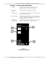
Guardian Jr. Alarm Activation
The audio and visual alarm will activate approximately six seconds after an
alarm condition is detected. To temporarily mute the audible alarm, press
and release the test/reset button.
NOTE:
After an alarm condition has been detected, the red light will stay
on. The audible alarm will remain muted until airflow returns to normal
levels.
Guardian Jr. Alarm Test
When no alarm is present the alarm can be tested by pressing the test/reset
button. While the button is pressed, the alarm light and audible alarm will be
activated.
Guardian Digital 1000 Operation
The Guardian Digital Airflow Monitor consists of the airflow sensor; the
Alarm Unit and the 15 VDC power supply. For 115V operation the alarm
unit is powered by plugging the power supply into the factory-prepared
digital airflow monitor socket. For 230V operation, the Alarm Unit is
powered by plugging the power supply into a building outlet. The alarm has
“Enter”, “+”, and “-” buttons to program the monitor. There is also a green
LED “SAFE”, yellow LED “CAUTION”, and red LED “LOW” with audible
alarm for airflow conditions. The audible alarm can be permanently muted if
desired. The Guardian Digital 1000 Airflow Monitor displays a face velocity
value, provides an RS232 communications port to a PC or building computer
system, can be configured for external input connections such as night
setback or external alarm and provides up to three output relays that can be
configured. For complete detailed information, please refer to the separate
Labconco 1000 Alarm User’s Manual provided with the enclosure.
Guardian Digital 1000 Installation Procedure
1. The enclosure comes prepared to except the Guardian™ 1000 Digital
airflow monitor system.
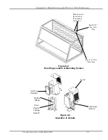
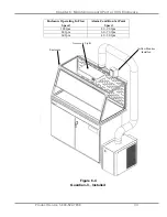
2. First remove the large 1.19" dia. gray hole plug and loosen the two
hardware nuts from the enclosure. Keep the nuts for step 3. See Figure
6-2. See Figure 6-5 only to reference internal assembly of the airflow
monitor.
3. Secure the Guardian Digital alarm to the enclosure with the two hardware
nuts removed from step 2. If the hardware stud drops from behind the
rear baffle, then tilt the baffle and hold it up to install.
4. The airway passage between the alarm module and the enclosure is now
complete.
Summary of Contents for Protector XVS Series
Page 49: ...Chapter 7 Accessorizing your XPert or XVS Enclosure Product Service 1 800 522 7658 45...
Page 54: ...Appendix A Replacement Parts Product Service 1 800 522 7658 50...
Page 56: ...Appendix B Dimensions Product Service 1 800 522 7658 52 2 3 and 4 Units...
Page 57: ...Appendix B Dimensions Product Service 1 800 522 7658 53 2 3 and 4 Units...
Page 58: ...Appendix B Dimensions Product Service 1 800 522 7658 54...

