background image

Chapter 8: Troubleshooting 


Product Service 1-800-522-7658 

51 


PROBLEM 

CAUSE 

CORRECTIVE ACTION 

Lights do not work

Lamp not installed 
properly. 

Inspect lamp installation. 


Lamp wiring disconnected. 

Inspect lamp wiring. 


Defective lamp. 

Replace lamp. 


Light switch is defective. 

Replace light switch. 


Defective electronic 
ballast. 

Replace ballast. 

Airflow monitor 
malfunction. 

No power. 
No lights. 
No display. 

Power cable to circuit board is disconnected and 
needs to be connected.  Sensor cable needs to be 
connected. Power supply is not plugged into 
proper voltage; plug in power supply.  Verify that 
all airflow monitor interface cables are 
connected.  Check fuses on enclosure. 


No audible alarm. 

Alarm has been temporarily silenced using 
“SILENCE ALARM” or “enter” buttons. 


Wrong alarm set point. 

Airflow monitor was not properly adjusted.  
Repeat calibration steps outlined in this manual in 
Chapter 6 or in the supplied Digital 1000 Monitor 
Manual. 


Constant audible alarm. 

Check airflow and calibration of airflow monitor. 
See Chapter 6. 


Continuous alarm. 

Check the face velocity of the enclosure as the 
airflow of the system may have changed.  If 
incorrect, adjust the speed control to increase face 
velocity.  The ULPA filter may have become 
loaded. If face velocity is correct, calibrate the 
airflow monitor outlined in this manual in 
Chapter 6. 


Monitor alarms; air way to 
airflow monitor sensor is 
blocked by insects, dust or 
debris. 

Lightly clean the airway with clean air.  Be 
careful not to touch sensitive electrical 
components. 


Audible disable will not 
stay operational. 

An alarm condition must be continuously present 
before the audible alarm can be silenced.  If flow 
conditions fluctuate near the alarm set point, the 
airflow monitor will automatically reset it.  
Action should be taken to bring the enclosure 
airflow into proper operating parameters or adjust 
the alarm set point lower. 


Summary of Contents for XPert 38872 Series

Page 1: ...XPert Nano Enclosures Models 38872 Series 38873 Series 38874 Series 38875 Series 38876 Series 38885 Series 38886 Series...

Page 2: ...rs of 7 30 a m and 5 30 p m Central Standard Time Part 3881800 Rev J ECO L352 Warranty Labconco Corporation provides a warranty to the original buyer for the repair or replacement of parts and reasona...

Page 3: ...ctrical Supply Source to the Nano Enclosure 14 Set the Face Velocity with the Speed Control Adjustment 14 CHAPTER 4 HIGH PERFORMANCE FEATURES AND SAFETY PRECAUTIONS 16 High Performance Features 16 Saf...

Page 4: ...er Replacement 41 Speed Control Replacement 42 Maintenance on the Optional Ionizer 43 Trace Odor Carbon Filter Installation 44 CHAPTER 7 ACCESSORIZING THE NANO ENCLOSURE 45 Guardian Airflow Monitors 4...

Page 5: ...ake full advantage of them please acquaint yourself with this manual and keep it handy for future reference The XPert Nano Enclosures include a true bag in bag out ULPA filter to properly protect pers...

Page 6: ...t in injury to the user or permanent damage to your Clean Bench Important information is presented in capitalized type in paragraphs that are preceded by the pointer icon It is imperative that the inf...

Page 7: ...The exhaust and blower requirements The electrical power requirements The space requirements Refer to Appendix B Dimensions for complete enclosure dimensions Refer to Appendix C Specifications for co...

Page 8: ...ates Do not place the balance and enclosure on a bench that would receive direct sunlight Humidity and Static Electricity Requirements Electrostatics can be troublesome in a balance enclosure It is im...

Page 9: ...ms per square The table below lists the surface resistivity of various classes of material Surface Resistivity Table Material Surface Resistivity Example Conductive 0 105 per square Skin Metals Static...

Page 10: ...CFM XPert Station Initial Static Pressure Loss with HEPA filter in w g XPert System Noise Pressure db A Xpert System Max Equivalent Resistance Ft Xpert System Max External Static Pressure 2 9 4 Sash 6...

Page 11: ...onnecting the filtered enclosure or other equipment such as a balance for weighing operations The enclosures include iris pass thru to allow electrical cords through the back of the enclosure without...

Page 12: ...th the speed control adjustment Arrange validation for the enclosure Depending upon which model you are installing you may need common mechanical and electrical installation tools in addition to wrenc...

Page 13: ...OU MUST FILE A CLAIM DIRECTLY WITH THE FREIGHT CARRIER LABCONCO CORPORATION AND ITS DEALERS ARE NOT RESPONSIBLE FOR SHIPPING DAMAGES Do not discard the packing material until you have checked all of t...

Page 14: ...d into its final location For stands with leveling feet use a carpenter level to adjust in both planes as shown in figure below 4 XPert Nano Enclosures have an integral stainless steel work surface wi...

Page 15: ...as shown in Figure 3 3 For the 2 3 and 4 sizes the exhaust connection ships uninstalled on the top and needs to be fastened with the screws provided See Chapter 7 for ordering Canopy Exhaust Connecti...

Page 16: ...Chapter 3 Getting Started Product Service 1 800 522 7658 12 Figure 3 2 FOR 6 NOMINAL EXHAUST DUCT CONNECTION 6 06 ID ON THE 2 3 AND 4...

Page 17: ...Chapter 3 Getting Started Product Service 1 800 522 7658 13 Figure 3 3 10 NOMINAL ON THE 5 AND 6 10 06 ID...

Page 18: ...elocity measurements are made using an anemometer An electric anemometer can be obtained from your laboratory supply dealer To determine the actual face velocity at the sash opening airflow velocity r...

Page 19: ...hapter 3 Getting Started Product Service 1 800 522 7658 15 NOTE Face velocity profiles and smoke testing should be performed frequently per your organization s quality system to ensure safe performanc...

Page 20: ...aerodynamic designs of the upper sash foil side air foils lower air foil upper dilution air supply and rear perforated baffle all work in concert to produce horizontal airflow patterns that significan...

Page 21: ...Chapter 4 Performance Features and Safety Precautions Product Service 1 800 522 7658 17 Not Shown 9 10 11 12 17 18 19 20 21 23 24 Figure 4 1 22 14 8 13 3 2 15 1 5 6 7 4...

Page 22: ...air foil air continues to pass under the air foil and through the Clean Sweep openings See Figures 4 1 and 4 3 The air foil is easily removable for cleaning Do not operate the enclosure without the a...

Page 23: ...for loading and cleaning The sash must be down for normal operation The 5 and 6 units utilize a gas spring assist in place of the latch 7 Utility Ports allow electrical cords and data cords to pass th...

Page 24: ...exhaust transition adapter designed for 6 diameter nominal duct on 2 3 and 4 sizes The 5 and 6 sizes use 10 nominal duct 21 Optional Ionizer not shown when activated floods the work area with positiv...

Page 25: ...t the concentration of flammable or explosive gases or vapors Use of an open flame should be avoided in the enclosure as they may disrupt the airflow patterns in the cabinet Gases under high pressure...

Page 26: ...enclosure 20 Proper operation of the enclosure depends largely upon the enclosure location and the operator s work habits The enclosure should be located away from traffic patterns doors fans ventila...

Page 27: ...y raise the sash for loading and cleaning Check the baffle air slots for obstructions Allow the enclosure to operate unobstructed for 1 minute Wear a long sleeved lab coat and rubber gloves Use protec...

Page 28: ...rticulate matter hazardous powders and biohazardous materials Because room air is drawn through the enclosure during operation this enclosure should not be used for operations requiring sample protect...

Page 29: ...ntrol switch allows the blower to be operated independently of the ionizer Push the top of the switch to activate the blower only push the bottom to energize the ionizer along with the blower The gree...

Page 30: ...otorized impeller and stainless steel interior should not be exposed to acids Where applications require the use of acids a separate ventilated enclosure or vented fume hood should be used with a remo...

Page 31: ...ing the inflow face velocity Operating and calibrating the airflow monitors Initial certification Re certification Fluorescent light replacement Motorized impeller replacement Speed control replacemen...

Page 32: ...on technician See Certification and Recertification in this chapter All monthly activities Decontamination When used in conjunction with biohazards the XPert Nano Enclosure should be decontaminated wi...

Page 33: ...e Figures 4 1 and 4 2 4 Place both arms in the rear gloves of the bag and carefully draw the HEPA filter out of the enclosure Rest the HEPA filter on the floor table or cart Remove arms from bag glove...

Page 34: ...n the bag Reinstall the front panel Figure 6 0 Figure 6 1 Bag In Bag Out Filter Changing Procedure Diagram Filter Leak Test Diagram Old Filter New Filter Old ULPA Filter Sealed in Old Bag Filter Gaske...

Page 35: ...g during operation Air Techniques Inc Model TDA 4A or equal One nozzle at 10 psig is 67 5 cfm x 100ug l Vol of air For the 2 at 90 fpm or 130 cfm one nozzle 10 psig is 6 750 130 cfm 52 ug l For the 3...

Page 36: ...ore than 1 inch from the surface of the filter media Scan the entire periphery of the filter and the gasket between the filter frame and the enclosure frame Scanning shall be done at a traverse rate o...

Page 37: ...y time the airflow is safe good one can press the SILENCE ALARM test button and the audio alarm and the red LED will turn on as long as this button is held down The circuit board has also a two pin co...

Page 38: ...ty Once the alarm condition is met simply increase the speed control outlined in Chapter 6 or replace the ULPA filter if the speed control is maximized 8 The table below lists typical alarm conditions...

Page 39: ...Chapter 6 Maintaining the Nano Enclosure Product Service 1 800 522 7658 35 Figure 6 2 Guardian Airflow Monitor LED with Airflow Switch...

Page 40: ...or external alarm and provides up to three output relays that can be configured For complete detailed information please refer to the separate Labconco 1000 Alarm User s Manual provided with the encl...

Page 41: ...ENTER button repeatedly until the CAL CONFIG MENU is displayed 4 In the CAL CONFIG MENU set for the following CALIBRATION CONFIG MENU SETTINGS DISPLAY UNITS FPM LOW AIR ALARM SEE CHART ABOVE LOW AIR...

Page 42: ...p out of the way wait approximately 30 seconds for air currents to settle and hit ENTER The airflow alarm will sample the airflow 5 Adjust the speed of the fan until the high airflow velocity is reach...

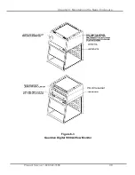
Page 43: ...Chapter 6 Maintaining the Nano Enclosure Product Service 1 800 522 7658 39 Figure 6 3 Guardian Digital 1000 Airflow Monitor...

Page 44: ...ghting Intensity Test when appropriate Noise Level Test when appropriate Vibration Test when appropriate Fluorescent Light Replacement 1 Disconnect the power 2 Locate the small light reflector located...

Page 45: ...ventilateur tant qu il est en marche 1 Wear appropriate personal protective equipment to decontaminate the filtered enclosure and then unplug from the electrical outlet 2 Remove filter per the ULPA fi...

Page 46: ...lding the speed control using a Phillips screwdriver Refer to Appendix A for Replacement Parts Diagram 3 Disconnect all wires leading to the speed control Connect wires on new speed control in the sam...

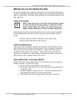
Page 47: ...lectronic grade isopropyl alcohol and 50 de ionized water Emitter Point Replacement If the ionizer fails to neutralize charges in the airstream the only portions of the ionizer that can be serviced ar...

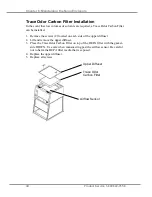
Page 48: ...ed 1 Remove the screws 2 located on each side of the upper diffuser 2 Lift and remove the upper diffuser 3 Place the Trace Odor Carbon Filter on top of the HEPA filter with the gasket side DOWN Use ca...

Page 49: ...Pert enclosures Description Order Part s Individual Parts Required Guardian Airflow Monitor 115V or 230V 1 ea 3811500 Airflow Monitor Printed Circuit Board 1 ea 3910700 Airflow Sensor w Connector 2 ea...

Page 50: ...leaks See Figure 3 3 and Figure B 3 Order the following Part Description 3924400 2 Canopy Exhaust Connection 6 3924401 3 Canopy Exhaust Connection 6 3924402 4 Canopy Exhaust Connection 6 3924403 5 Can...

Page 51: ...Blower 115V 60 Hz 4 5 A 720 950 760 1050 710 1060 620 1060 7068400 1 3 Remote Blower 115V 60 Hz 6 1 A 760 1050 710 1060 620 1060 430 1060 460 1150 500 1220 7068500 1 3 Explosion Proof Blower 115V 60...

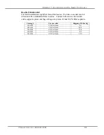
Page 52: ...5 and 6 have two each Filter Classification and Size Catalog X Pounds 2 Organic 18 x 18 x 1 3937200 5 5 lbs activated 3 or 6 Organic 30 x 18 x 1 3937300 9 2 lbs Activated 2 required on 6 4 Organic 42...

Page 53: ...Provides a second level of filtration with a redundant filter in series Contact Labconco as kit include entire support system and bag in bag out system Order ULPA filter separate Catalog For use with...

Page 54: ...al Ref Appendix D Enclosure has improper face velocity Have enclosure certified and check exhaust system Check filters for loading Adjust enclosure speed control Enclosure should have an average face...

Page 55: ...ion steps outlined in this manual in Chapter 6 or in the supplied Digital 1000 Monitor Manual Constant audible alarm Check airflow and calibration of airflow monitor See Chapter 6 Continuous alarm Che...

Page 56: ...Chapter 8 Troubleshooting Product Service 1 800 522 7658 52 Service Operating Record Log Customer Name Model Number Date Installed Serial Number Unit Location Date Comments...

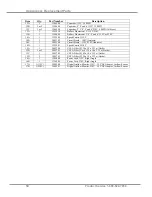
Page 57: ...2 Lamp Fluorescent 3 Enclosure F17T8 6C 1 9721901 Lamp Fluorescent 4 Enclosure F25T8 6D 1 9721900 Lamp Fluorescent 5 F32T8 6E 1 9721903 Lamp Fluorescent 6 F40T8 6F 1 9721910 LED 5 Enclosure 48 nominal...

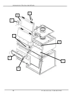
Page 58: ...5V 14B 1 3885302 Circuit Board 100V Ionizers 14C 1 3885300 Circuit Board 115V 230V Ionizers 14D 1 1325501 Speed Control 230V 15A 1 3885700 ULPA Filter 2 18 x 18 x 3 32 w Gasket 15B 1 or 2 3885701 ULPA...

Page 59: ...Appendix A Replacement Parts Product Service 1 800 522 7658 55 15 16 10 12 14 2 1 5 6 7 9 3...

Page 60: ...Appendix A Replacement Parts Product Service 1 800 522 7658 56 17 4 17 17 8 7 10 15...

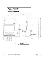
Page 61: ...Product Service 1 800 522 7658 57 Appendix B Dimensions See the following dimensions and exhaust options for all the XPert Nano Enclosures Figure B 1 XPert Nano Enclosure 2 3 and 4...

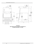
Page 62: ...Appendix B Dimensions Product Service 1 800 522 7658 58 Figure B 2 XPert Nano Enclosure with Duct Connection or Canopy Connection 2 3 and 4...

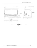
Page 63: ...Appendix B Dimensions Product Service 1 800 522 7658 59 Figure B 3 5 and 6 x 35 64 Deep XPert Nano Enclosure...

Page 64: ...Appendix B Dimensions Product Service 1 800 522 7658 60 Figure B 4 5 and 6 x 29 13 Deep XPert Nano Enclosure...

Page 65: ...Appendix B Dimensions Product Service 1 800 522 7658 61 Figure B 5 5 and 6 x 35 64 Deep XPert Nano Enclosure...

Page 66: ...Appendix B Dimensions Product Service 1 800 522 7658 62 Figure B 6 5 and 6 x 29 13 Deep XPert Nano Enclosure...

Page 67: ...ve humidity 80 for temperatures up to 88 F 31 C decreasing linearly to 50 relative humidity at 104 F 40 C Main supply voltage fluctuations not to exceed 10 of the nominal voltage Transient over voltag...

Page 68: ...4x18x3 31 2 18x30x3 31 Motor Horsepower HP 0 13 0 13 0 30 0 60 0 60 Capacitor MFD Volts 10MFD 115V 2 4MFD 230V 10MFD 115V 2 4MFD 230V 15MFD 115V 4MFD 230V 15MFD 115V 4MFD 230V 15MFD 115V 4MFD 230V Flu...

Reviews: