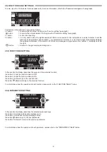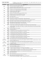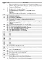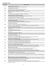
43
FUNCTION
STATE
EXPLANATION
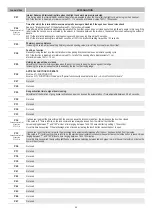
F23
1
OFF
OPEN input configuration: normally closed contact. When a device with N.C. contact is installed
ON
OPEN input configuration: normally open contact. When not in use or if a device with N.O. contact is installed
F24
1
OFF
STOP/INTERLOCK input configuration: normally closed contact N.C.
ON*
STOP/INTERLOCK input configuration: normally open contact N.O.
F25
OFF
In case of failure of the closing safety sensor test, the door stays open
ON
In case of failure of the closing safety sensor test, the door closes slowly after 30 seconds
F26
OFF*
Pause time with open door before constant automatic closing.
ON
Automatic increase of the pause time with door open if the door cannot close due to the high flow of people.
F27
OFF*
Interlock function disabled.
ON
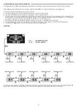
Function of interlock between two doors enabled. A door may be opened only if the other one is closed. See para. "Interlock system".
F28
Function active if
F27 = ON
OFF*
In interlock function, door opening is delayed by 0.5" after the opening command. See para. "Interlock system".
ON
In interlock function, door opening is immediate after the opening command. See para. "Interlock system".
F29
Function active if
F27 = ON
OFF*
In interlock function, the opening control on the closed door is not saved. See para. "Interlock system".
ON
In interlock function, the opening command on the closed door is saved and the subsequent opening will take place as soon as the other door will be closed.
See para. "Interlock system".
F30
OFF*
Operation with automatic closing
ON
"Step by step" function on the START or OPEN inputs. Below is described the operative mode for each input:
START INPUT: one pulse opens, a second pulse during opening stops, a third pulse closes.
OPEN INPUT: one pulse opens the door completely, a second pulse closes it.
F31
OFF*
"Man presence" operation off.
ON
"Man presence" operation on. The START input controls hold to run door opening. When the command is released, the door stops. The AUX2 input controls
hold to run closing. When the command is released, the door stops.
F32
OFF*
The "step by step" mode works as described in function F30 = ON.
ON
The step by step function works with the opening and closing controls on two separate inputs of the automation electronic control unit ET‑LOGIC‑B.
The inputs START and OPEN control opening, AUX2 controls closing.
F33
OFF*
Switching from reduced opening during winter to full opening inactive.
ON
Switching from reduced opening during winter to full opening active. If the door cannot close due to the high flow of people, after approximately one minute it
switches from reduced opening to full opening.
F34
OFF*
Dynamic reduced opening during winter OFF.
ON
Dynamic reduced opening during winter ON. In the work program "winter reduced opening", if both internal and external radars are engaged at the same time,
the door opens fully.
F35
OFF*
Energy saving function OFF.
ON
Energy saving function ON. The door closes back as soon as the opening radars and the closing safety sensors are no longer engaged, to minimise the
amount of time during which the door stays open.
To maximise the benefit of this function, it is recommended to install single-direction activation sensors.
F36m
Multiple selection
function
Multiple selection function that allows to set the "Manual free door program" in the mechanical key selector
EV‑MSEL, replacing in the chosen position the standard program.
A*
Standard operation of the EV‑MSEL mechanical selector (Manual free door program not enabled)
B
Manual free door program enabled in "exit only" position
C
Manual free door program enabled in "Night lock" position
D
Manual free door program enabled in "Reduced opening during winter" position
F38
OFF*
START input: it is enabled to open the door in any door work program.
ON
START input: it is enabled only when the automatic programs are selected. It doesn't open the door when the Night Lock program is selected.
Note 1:
do not select ON if you use the LABEL radio control with a EN/RF1 radio receiver to open the door in the night lock program.
Note 2:
do not select ON if you set the switching into stand by function → F10=ON
F39
OFF
The F1 button of the selector ET‑DSEL or the button B of the selector T‑NFC controls door opening in automatic programs only.
ON*
The F1 button of the selector ET‑DSEL or the button B of the selector T‑NFC controls door opening in both automatic and NIGHT LOCK programs.
F40
OFF*
It enables the warning beep by the buzzer when the motor thrust power limit is reached. Please refer to the "Functional testing" paragraph
See para. "Functional testing"
ON
It disables the warning beep by the buzzer when the motor thrust power limit is reached.
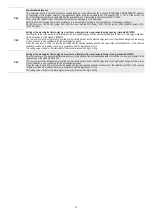
Multiple selection function that allows to set the modes of operation of the output OUT1 for the relay module UR24E.
WARNING! If you have selected the interlock function → F27=ON, the output OUT1 operates as interlock signal and all the functions provided for by F41m are
automatically disabled.
F41m
Multiple selection
function
A
The output displays the state of the input LOCK1 of the control unit ET‑LOGIC‑B. Output active with closed contact, inactive with open contact.
This function can be used to indicate the state of the electric lock and the position of the leaf when you install the electric lock with microswitch.
B
Door crossing warning gong The GONG function is an entry warning triggered by the activation of the closing safety sensor while the automatic door is being
crossed. Please refer to the "Gong function" paragraph.
C*
Air curtain (device generating a flow of cold or heated air to separate the outside temperature from the inside one).
The output turns on when the door is moving, whereas it turns off when the door is closed.
D
Battery state. The activation of the output reports the status of damaged battery.
E
Door state display. Slow flash during opening, permanently lit with the door open, fast flashing during closing, off with door closed.
F
Alarm warning.
The output activates for 2 seconds if with door closed in Night Lock an opening radar or a safety closing sensor activate.
G
Maintenance signal
The output activates when the door reaches the number of cycles provided for by the maintenance plan set by the potentiometer P48.
H
The output signals the activation of the STOP input or of the photocell PRJ38 operating as motor stop sensor.


