


33
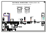
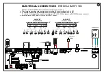
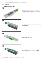
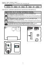
Insert the other terminal of the cable to J7 connector on the control unit ET-LOGIC EASY.
After completing all the electrical connections to the electronic control unit of the automation, power the
automatic door.
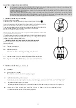
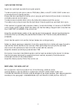
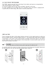
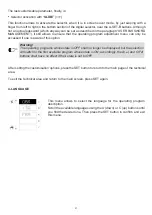
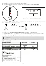
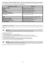
When installed for the first time, the selector shall automatically
switch to the language selection menu.
Scroll the available languages using the A (down) or C (up) buttons
until you find the desired one. Now press the SET button to confirm
and exit this menu.
The language shall be saved and you shall no longer have to select
it again. Should you later wish to change the language, access
menu 5 from the technical area and repeat the operation.
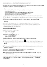
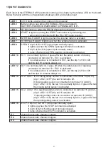
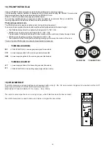
Once the language has been chosen the selector will automatically
start detecting the doors existing on the serial communication line
(up to 2); the data will be stored in the processor. During this step the
“WAIT” message will be displayed on the alphanumeric character
line. Wait for this step to be completed before you touch any button.
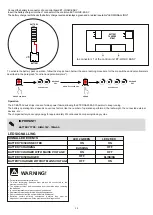
Warning!
The detection operation shall be automatically performed every time the door is powered,
and shall take a few seconds.
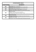
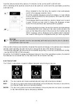
If the operation has been successfully completed the selector will display on the alphanumeric character
line the saved operating program for the door, along with its text, in the desired language.
The following paragraph provides a list of the available programs (you can also customise their visibility
- see the SELECTOR OPTION chapter).
Should the “ NO COMM” message be displayed instead of one of the operating programs, the selector
has detected no connected door. In this case check the connection and retry.
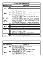
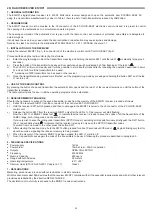
DAY-TO-DAY USE
The T-
EASY
model allows to select 6 different program types for day-to-day use:
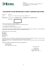
AUTO:
The door opens and closes automatically both ways with all sensors activated
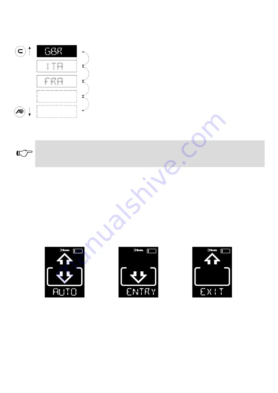
EXIT:
The door only opens and closes automatically in the exit direction: the sensor connected to
the External Radar input is temporarily disabled.
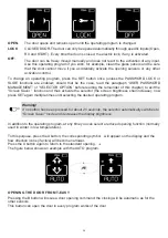
ENTER:
The door only opens and closes automatically in the entry direction: the sensor connected
to the Internal Radar input is temporarily disabled.
Summary of Contents for ETERNA 90 EASY
Page 47: ...47 notes ...