background image

45

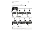
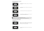
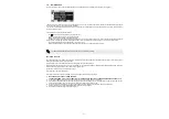
21) 

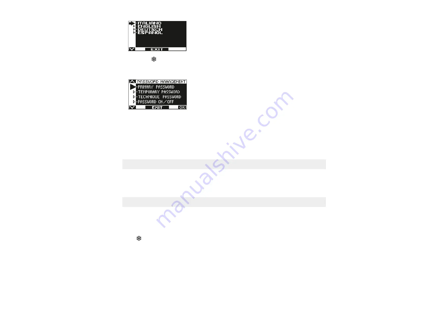
LANGUAGE


Ÿ

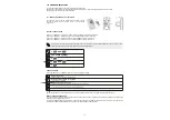
Use the F2 and         buttons to move arrow to the desired language.

Ÿ

Press EXIT (SET) button to return to general programming menu.

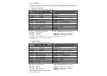
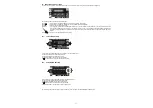
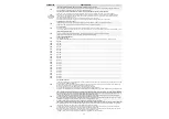
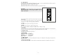
22) PASSWORD MANAGEMENT


This section shows three types of password.


a)  TECHNICAL PASSWORD (for technical personnel in charge of installation and maintenance)

It is the 10-character password of the installer who starts the system.
Using the technical password is compulsory to prevent unauthorized persons from having access to general programming menu sections 
concerning parameters and functions setting, initial set-up and maintenance area.
Default preset technical password is “A-A-A-A-A-A-A-A-A-A”.

WARNING!
It is recommended to change the default technical password and be very careful not to forget it.

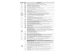
b)  PRIMARY PASSWORD (for the system's owner-user)

It is a 5-character password used by the user to prevent unauthorized persons from having access to ET-DSEL programmer and change the 
work program.
Using a primary password is optional and must be enabled by system's owner.
Default preset primary password is “A-A-A-A-A”.

WARNING!
When enabling the password, be careful not to forget the access combination.

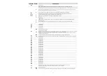
c)  TEMPORARY PASSWORD (for user)

It is a 5-character password that the system's owner may divulge to persons to be authorized to use ET-DSEL programmer.
The service password only allows changing the automatic door work program.
Default preset service password is “A-A-A-A-A”.
To change the service password, it is necessary to have access by primary password.

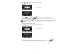
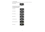
Use the         button to move the selection arrow downward and the F2 button to move the arrow upward.


Summary of Contents for ETERNA 90

Page 1: ...Automation for automatic sliding doors ETERNA 90 1 1 GB Rel 1 01 20 9 CD0709EN EN TRANSLATION OF THE ORIGINAL INSTRUCTIONS ETERNA 90 INSTALLATION MANUAL ...

Page 2: ... AUTOMATION 5 MECHANICAL COMPONENTS OF THE ETERNA 90 SLIDING DOOR AUTOMATION 3 ETERNA 90 AUTOMATION COMPONENTS 6 4 TECHNICAL DRAWINGS COMPONENT ARRANGEMENT 7 5 COVERING CASING 9 6 BELT TIGHTENING ADJUSTMENT 10 7 MECHANICAL LIMIT DEVICE POSITIONING 10 8 LEAF ANCHORING TO THE CARRIAGES AND ADJUSTMENT 10 9 INSTALLATION DIMENSIONS 12 10 ELECTRIC LOCKS 14 ...

Page 3: ...MENU 38 20 FUNCTIONS AND SETTINGS 39 20 1 FUNCTION SETTING 39 20 2 PARAMETER SETTING 39 FUNCTION TABLE 40 PARAMETER TABLE 43 21 LANGUAGE 45 22 PASSWORD MANAGEMENT 45 22 1 HOW TO CHANGE THE TECHNICAL PASSWORD 46 22 2 HOW TO CHANGE THE PRIMARY PASSWORD 46 22 3 HOW TO CHANGE THE SERVICE PASSWORD 47 22 4 ENABLING USER PASSWORD USAGE 48 22 5 DISABLING USER PASSWORD USAGE 48 23 SELECTOR OPTIONS 49 24 IN...

Page 4: ...dossier must be prepared for every automation as required by the Machine Directive Disconnect the power supply before working on the automation and before opening the cover Maintenance is of fundamental importance for the proper operation and safety of the automation Check the efficiency of all parts every six months Use only original spare parts for maintenance and when replacing product componen...

Page 5: ...ION OF THE MODELS The ETERNA90 automation has been designed and manufactured for the control of pedestrian automatic sliding doors Alist of the ETERNA90 sliding door automation models produced by Label is provided below Ÿ ETERNA90D Automation for double door leaf max weight 90Kg leaf Ÿ ETERNA90S Automation for single door leaf max weight 130Kg The choice of the model depends on the type of door to...

Page 6: ...COMPONENTS 13 14 12 15 16 2 1 3 4 side panel pair ET LOGIC B electronic control unit ET MOT 90 motor unit with encoder fall prevention cables double wheel carriage 5 10 6 7 8 9 upper belt coupling lower belt coupling cable gland return pulley mechanical limit switch driving belt 11 10 ...

Page 7: ...OR LEAF WITHOUT ELECTRIC LOCK LC BELT LENGTH LC F M 80 x2 M MOTOR PULLEY M LT 1 4 80 F IDLE PULLEY LT 3 4 250 LM LEAF WIDTH LM LT B 4 S 2 10 PL FREE PASSAGE PL LT B 2 S 10 LT TRANSOM LENGTH LT 2PL B 2S 20 LC BELT LENGTH LC F M 80 x2 M MOTOR PULLEY LT LM 250 F IDLE PULLEY LT 120 LM LEAF WIDTH LM LT B S 2 10 PL FREE PASSAGE PL LT B S 2 10 LT TRANSOM LENGTH LT 2PL B S 20 F M F M F M LEGEND LT AUTOMAT...

Page 8: ...LT LENGTH LC F M 80 x2 M MOTOR PULLEY LT LM 250mm F IDLE PULLEY LT 120 LM LEAF WIDTH LM LT B S 2 10 PL FREE PASSAGE PL LT B S 2 10 LT TRANSOM LENGTH LT 2PL B S 20 E ELECTRIC LOCK LT 102mm LC BELT LENGTH LC F M 80 x2 M MOTOR PULLEY LT LM 250mm F IDLE PULLEY LT 120 LM LEAF WIDTH LM LT B S 2 10 PL FREE PASSAGE PL LT B S 2 10 LT TRANSOM LENGTH LT 2PL B S 20 E ELECTRIC LOCK 90mm F M E M F E 8 F M E LEG...

Page 9: ...acing the same direction FIG 2 Icarter dell automazione ETERNA 90 è dotato di due cavetti paracadute A sudiati appositamente per mantenerlo stabile nella posizione di apertura FIG 1 Posizionare il carter sull automazione facendo agganciare la parte superiore con la traversa FIG 3 e chiuderlo premendo verso il basso Per togliere il carter dall automazione rimuovere le viti di fissaggio premere la p...

Page 10: ...position then fully tighten the 2 screws again FASTENING SCREWS 10 FIG 6 FIG 7 8 ANCHORING THE LEAVES TO THE CARRIAGES AND ADJUSTING THEM Unscrew the two front screws A of every carriage and remove the movable part C Secure the disassembled mobile part C on the door at the distance shown in the figures from 9 to 12 depending on the type of automation Now hang the leaf to the automation matching th...

Page 11: ...OOR LEAF WITH ELECTRIC LOCK 65 120 175 65 120 175 65 120 175 65 120 175 120 175 230 65 120 175 FIG 11 LEFT CLOSING SINGLE LEAF WITH ELECTRIC LOCK FIG 12 RIGHT CLOSING SINGLE LEAF WITH ELECTRIC LOCK 65 120 175 65 120 175 65 120 175 65 120 175 120 175 230 65 120 175 ...

Page 12: ...the transom L1 and L2 every 300mm The figure shows the fastening dimensions When drilling the transom and the wall take care not to damage the sliding rail B1 as that would affect the operation and the quietness of the automated equipment After fastening the transom thoroughly clean the sliding area from any drilling scraps 12 FIG 13 FIG 14 REQUIRED TOOLS Tape measure drill level thin flat head sc...

Page 13: ...WITH COMMERCIAL PROFILES LT automation length LT 2PL B 2S 20 13 ETERNA 90D 2 MOBILE LEAVES 9 9 3 12 A A 9 9 6 10 Distanza Massima dalla Parete PAD PADKIT Guida a Pavimento 2NC5947 A1S MG773S S PT1 LEGEND LT AUTOMATION LENGTH PL FREE PASSAGE LM LEAF WIDTH B FINALLEDGES S LEAF OVERLAPPING S S B LM LM PL LT S LT PL B LM 2000 2500 3000 3500 4000 4500 5000 5500 6000 512 637 762 887 1012 1137 1262 1387 ...

Page 14: ...RAWINGS The electric lock is fastened to the automation by 2 M6 X 10 screws on M6 nuts in the special lower slot in the transom The sliding carriages must be regulated so that when the leaf is in closed position the electric lock piston can hook the carriage bracket and keep the leaves locked The electric lock kit includes a power supply cable This cable has two wires on one end that are connected...

Page 15: ...ves freely C Secure the bottom of the release handle to the side panel using the self tapping screws provided Respect the positions indicated in the opposite figure RELEASE HANDLE FASTENING A B For fastening on both the right and left side of the automation you need to fasten the adjustment register on the bottom of the release handle Insert the steel cable inside the flexible sheath as shown in t...

Page 16: ...end into the release handle as shown in the figure and fasten the handle to the bottom with the special screw SCREW COVER LABEL Apply the screw cover label on the fastening screw By moving the release handle to the UNRELEASED position only the orange part of the label with the drawn arrows must be visible D E F Insert the flexible sheath inside the side panel LEFT SIDE PANEL RIGHT SIDE PANEL 16 ...

Page 17: ...nto the release handle and into the sheath until reaching the electric lock Fit the sheath end on the tip of the sheath which has been cut Position the compression spring and insert the metal cable inside the special release anchor then lock it with the screw clamp Adjust cable tightening so as to give the spring a light pre load 17 ...

Page 18: ...se the leaves Cut the excess steel cable from the release anchor NOTE In case of FAILSECURE electric lock by releasing the release the electric lock will close In case of a bistable electric lock by releasing the release it will open In case it is necessary to manually close the door with a bistable electric lock it will be sufficient to lift the core of the secondary solenoid with a screwdriver 1...

Page 19: ...respondence of the 4 cardinal points Insert the adjustment register using 2 nuts one in the plastic slot and the other outside of it BLACK BANDS BLACK BANDS FASTENING SCREW FASTENING SCREW Identify the fastening point on the wall taking into account that the standard cable sheath is 3 metre long and that it must reach the electric lock SCREW COVER LABEL 10 4 INSTALLATION OF THE MANUAL RELEASE ON T...

Page 20: ...ammer External movement and presence sensor for door opening and safety during closing Opening safety sensor Key button N 1 CABLE 8 x 0 5 mm DESCRIPTION OF ACCESSORIES CORRESPONDING CABLE N 1 CABLE 2 x 0 5 mm N 1 CABLE 4 x 0 33 mm a coppie twistate per RS485 N 1 CABLE 8 x 0 5 mm N 1 CABLE 6 x 0 5 mm N 1 CABLE 2 x 0 5 mm N 1 CABLE 3 x 1 5 F N T 7 20 ETERNA 90 automation 7 11 ELECTRIC ARRANGEMENTS ...

Page 21: ... 1 PRJ38P BATTERY 18V 1 2 3 4 12 10 16 17 RADAR INT COM AUX1 AUX2 EV MSEL BLUE BROWN BLACK SAFETY OUTPUT TEST POWER 8 E 0 1 22 24V 21 0 20 TEST 21 0 7 COMMON E O 2 SAFETY OUTPUT TEST POWER 9 E 0 2 22 24V 21 0 20 TEST 21 0 7 COMMON SAFETY OUTPUT TEST POWER 5 E C 1 22 24V 21 0 20 TEST 21 0 7 COMMON ACTIVATION 10 COMMON 12 RADAR IN SAFETY OUTPUT TEST POWER 6 E C 2 22 24V 21 0 20 TEST 21 0 7 COMMON AC...

Page 22: ...n the transom to the ground terminal on the electronic control unit The line is protected by 2 5Afuse F1 On the power supply mains foresee an omni polar switch selector with contact opening distance at least of 3 mm The power supply line must be protected against short circuit and dispersion to ground Separate the 230Vac power supply line from the very low voltage line control unit relative to con...

Page 23: ...ly close the door when function F52 is set to ON In this case the input must be configured as N C 15 LOCK1 input N O contact Closing the contact on the input activates the output of the UR24 module if optionAis selected on function F41 m or F45 m see UR24 Module paragraph 17 auxiliary AUX 2 N O Contact serving for two functions depending on the configuration set on the control board a Using the me...

Page 24: ...ative for the receiving capsule black cable TERMINAL BOARD M8 FT power supply positive of the transmitting capsule blue cable FT1 PRJ38 PHOTOCELL transmitting capsule signal brown cable M9 ET DSEL DIGITAL PROGRAMMER 1 2 3 13V B 0 4 A Photocell operation mode The PRJ38 photocell is used as a STOPsensor in the panic exit breakout system To ensure proper operation the photocells must be perfectly ali...

Page 25: ...Connect the ET DSELdigital programmer to the control unit of the ETERNA90 operator using a 0 33mm 4 wire cable with twisted pairs for RS485 applications Terminal 13V connect to terminal 1 of the ETERNA90 control unit 13V Terminal connect to terminal 4 of the ETERNA90 control unit GND Terminal A connect to terminal 2 of the ETERNA90 control unit A Terminal B connect to terminal 3 of the ETERNA90 co...

Page 26: ...wer the ETERNA90 operator by mains voltage the control unit buzzer emits some quick short beeps Language selection is shown on the display of ET DSELdigital programmer use the F2 and buttons to move arrow to the desired language Press EXIT button to exit Language section and enter Serial communication setups section as described under para 14 3 Power the ETERNA150 operator by mains voltage the con...

Page 27: ...ous function Select the automation model ON ETERNA90 OFF ETERNA150 300T If the ET DSEL digital programmer is connected to two automatic doors select by pressing the F3 button once whether the initial set up concerns the operator of door 1 or that of door 2 The initial set up must be carried out separately on each operator OPERATOR 1 OPERATOR 2 Select ON only if a safety sensor has been installed o...

Page 28: ...f ET LOGIC B board Select ON with normally open contact or when the OPEN input is not used Select OFF when using a device with normally closed contact Select ON only if a safety sensor has been installed on opening on input E O 2 Select ON only if a safety sensor has been installed on opening on input E O 1 Select ON only if a safety sensor has been installed on closing on input E C 2 If S09 and o...

Page 29: ...imensions and weight are close to the limits allowed A short noise signal by the buzzer during start in opening is to be considered as normal as the pick up phase is the moment requiring maximum force Adjust the thrust power by P04 parameter of ET DSELprogrammer see Adjustment of parameters paragraph To deactivate the buzzer noise signal when the power limit is reached set up F40 function to ON se...

Page 30: ...ng the hexagon socket head cap screws 4x6 A B C D Remove the container of the electronic control unit by unscrewing the two screws M5x10 Position the battery inside the plate Refit the container of the electronic control unit inserting the battery cable through the slot at the top and tighten the screws M5x10 To replace the battery perform the operations described in steps B C and D 30 ...

Page 31: ...g cycles IMPORTANT BATTERYTYPE NiMH 18V 700mAh Periodically check battery efficiency To allow recharging batteries must always be connected to the electronic control unit The equipment must be disconnected from the mains when removing the batteries In case of replacement always use genuine batteries Replacement must be performed by qualified personnel Remove batteries from the equipment before its...

Page 32: ...the consumption of the emergency battery to prevent it from discharging in a short time during a power failure To enable the stand by mode set function F10 ON To open the door during stand by mode an input is provided between terminals 28 29 Wake GND of the ET LOGIC B control unit to which must be connected a device with contact N O A pulse on the Wake input allows the control unit to be turn on a...

Page 33: ...NCTIONAL SETTINGS F12 S05 ON If the safety sensor is installed on E C 1 F13 S06 ON If the safety sensor is installed on E C 2 F16 S09 ON Closing safety sensor test enabled F18 S11 OFF LOW level test 17 2 OAM DUALT SENSOR OAM DUAL T SENSOR WIRING ETERNA 90 OPERATOR ET LOGIC B TERMINAL Correspondence between the sensor cables and the terminal board of the ET LOGIC B control unit 1 WHITE Power supply...

Page 34: ...10 ON Test input Low For information about the adjustments and the other sensor functional settings please refer to the instructions supplied with the OA PRESENCETsensor ET DSEL PROGRAMMER FUNCTIONAL SETTINGS F14 S07 ON If the safety sensor is installed on E O 1 F15 S08 ON If the safety sensor is installed on E O 2 F17 S10 ON Opening safety sensor test enabled F18 S11 OFF LOW level test The safety...

Page 35: ...ree door program can be selected by means of the EV MSEL selector to disable the automatic door automatic operation and to let the operator manually move the leaves To enable the MANUAL FREE DOOR program in the desired position of the EV MSEL mechanical selector operate on the F36m function combination on the ET DSELdigital programmer see para FUNCTIONS and SETTINGS Open door program The door stop...

Page 36: ...on external radar input Single direction automatic program input only To exclude the outgoing detection on internal radar input Open door program The door stops in complete opening position Night lock program The door can only be open by OPEN input or radio control if EN RF1 radio receiver is installed Free manual door The automatic operation is disabled and door can be manually open Power warning...

Page 37: ...INTENANCE message If the PROGRAMMED MAINTENANCE message appears on the display please contact the authorised support centre to request a system maintenance intervention Operation of other buttons located on ET DSEL program selector panel REDUCED OPENING DURING WINTER To reduce the passage opening To activate the reduced opening during winter press the button once The symbol on the display indicate...

Page 38: ...e a quick pulse on ENTER button To exit the general programming menu and return to the operating program view press EXIT F1 F1 F1 F1 5 SELECTOR OPTIONS UNUSED F1 F1 F1 Ÿ Refer to par 14 3 when entering the initial set up section Ÿ If entering the serial communication setting section please refer to para 14 2 Ÿ For the other sub menus refer to the following paragraph on the section you have had acc...

Page 39: ...r If the ET DSELprogrammer is connected to a single operator the number 1 appears at the top right of the display button to return to the general programming menu 20 1 FUNCTION SETTING In this section the display describes the purpose of the selected function the F1 button sets the function status to OFF the F3 button sets the function status to ON the F2 button allows to switch to the next functi...

Page 40: ...fect for entire opening stroke ON The activation of the safety sensor in opening E O 1 E O 2 has effect in the last 500mm of the opening stroke OFF The activation of the safety sensor during opening slows down the leaf opening motion until the end of the stroke is reached ON The activation of the safety sensor during opening stops the leaf motion until the obstacle is removed F031 F02 F07 F08 F09 ...

Page 41: ...RT input it is only enabled when the automatic programs are selected It doesn t open the door when the Night Lock program is selected Note 1 don t select ON if the Label radio transmitter with an EN RF1 radio receiver are installed to open the door in the night lock program Note 2 don t select ON if the function stand by switching F10 ON is enable OFF The F1 button of the ET DSEL digital programme...

Page 42: ...y inputs are disabled Should the forced closing device s ll be ac ve once the door is closed the only way to open the door will be using a held command on the OPEN input manned mode OFF The internal and external radars are not ac ve during the closing opera on in the night lock work program ON The internal and external radars are ac ve during the closing opera on in the Night Lock work program cau...

Page 43: ... reversal of the movement Increasing the value increases the pushing me and decreases the sensi vity P13 Reac on me to the obstacle during the slowing down phase in opening at slow speed Adjustment of the pushing me against the obstacle during the opening cycle at slow speed before the reversal of the movement Increasing the value increases the pushing me and decreases the sensi vity P14 Reac on m...

Page 44: ...generally protected by other safety devices as the kine c energy level is not regarded as dangerous The low energy mo on however is only considered for the risk assessment purposes When the value is set to 00 the func on is disabled and the opening speed can be set using the P01 poten ometer In this case the installer must take other safety measures in compliance with the regula ons in force The s...

Page 45: ...cal password and be very careful not to forget it b PRIMARYPASSWORD for the system s owner user It is a 5 character password used by the user to prevent unauthorized persons from having access to ET DSELprogrammer and change the work program Using a primary password is optional and must be enabled by system s owner Default preset primary password is A A A A A WARNING When enabling the password be ...

Page 46: ... password A A A A A A A A A A by pressing 10 times onAbutton Ÿ Type the new technical password selecting a combination of 10 characters from the lettersA B C D Ÿ It is required to repeat the new password so type the previous combination again Ÿ If the password typed is correct PASSWORD OK is shown on display for one second and the general programming menu is restored Ÿ Type the default preset prim...

Page 47: ... will switch back to the PASSWORD MANAGEMENTsection and the user will have to repeat the procedure Ÿ Type the primary password Ÿ Type the new service password selecting a combination of 5 characters from the lettersA B C D Ÿ It is required to repeat the new password so type the previous combination again Ÿ If the password typed is correct PASSWORD OK is shown on display for one second and the syst...

Page 48: ...oor work program the primary or service password must be typed When the user decides to enable the password usage it is recommended to change the combination of both primary and service password 22 5 DISABLING USER PASSWORD USAGE Ÿ From the PASSWORD MANAGEMENTsection select PASSWORD ON OFF Ÿ Press OK F1 button Ÿ Press OFF F1 button to disable user password usage To return to the general programmin...

Page 49: ...irectional program The buttons in this sub menu are used as follows The button allows to switch to the next function The F2 button allows to return to the previous function The F1 button sets the function status to OFF The F3 button sets the function status to ON Exit only program Entry only program Door open program Night lock program Free manual door program Reduced opening during winter Chemist...

Page 50: ...touch on F3 button allows to switch from 1 to 2 and vice versa Ÿ If the ET DSELprogrammer only manages a single operator the symbol 1 is displayed at the top right Ÿ The F1 button allows to switch to the event memory to display error messages press it again to return to the information area Ÿ The EXIT button allows to return to main view of the door work program 5 EVENT MEMORY ERROR I1 I2 I3 I4 I5...

Page 51: ...intervention pleaserefertothe Maintenance paragraph Itdisplaysthedooropening closingcycleswhichhavebeencarriedoutsincethefirststart upoftheoperator Refer to the following tables for the list of information and error messages The events memory stores the last 5 error messages in chronological order When all the 5 memory cells are full of messages the following event stored shall be located in E1 ce...

Page 52: ...FAULT BATTERY FAULT EEPROM REGISTER FAULT The motor piloting signal test has detected a fault Signals from the encoder are not detected Failed opening safety sensor test Failed closing safety sensor test The system signals a damage to the battery Failed internal memory register test OPENING OBSTACLE CLOSING OBSTACLE The door has come into contact with an obstacle while closing this caused the moti...

Page 53: ...control unit to the factory settings 25 1 PLUG and PLAY The PLUG and PLAY option allows you to configure the desired functions and parameters of the automatic door directly in the factory before sending the automation to the site for installation To adjust the functions and parameters refer to the paragraph Functions and Settings After selecting the desired functions enter in the SERVICE section o...

Page 54: ...ct on LOCK 1 input is closed B GONG The output is active for 2 seconds by crossing the automatic door Refer to the GONG FUNCTION paragraph for a detailed description of the GONG operation C AIR BLADE Air blade command Device that generates a cold or heated air flow to separate the external temperature from the internal temperature The output is active when the door is moving or open whereas it dea...

Page 55: ...se a 24Vdc supply is used by taking the power supply directly from terminals 21 22 of the ET LOGIC B control unit c To activate the GONG function use the ET DSEL digital programmer and set function F41m option B OUT1 or F45m option B OUT2 At this point each time that the safety sensors are operated when closing the door the GONG will sound for 2 seconds d To change the waiting time elapsing from w...

Page 56: ...io control opens the door in all the automation work programs 5 CANCELLATION OF THE MEMORYOF THE RECEIVER Should it be necessary to cancel all the saved transmitter codes from the memory of the EN RF1 receiver proceed as follows a Extract the EN RF1 receiver from the connector of the ET LOGIC B control unit b Keep the receiver SW1 button pressed and then couple again the EN RF1 receiver to the J9 ...

Page 57: ...ock input terminals 14 19 it allows to forcibly close the door at slow speed after the device activation During this closing operation all control and safety inputs are disabled Should the forced closing device still be active once the door is closed the only way to open the door will be using a held command on the OPEN input manned mode FIG 1 FIG 3 FIG 2 SPYC SPYC 1 3 MDW 1E MDW 2E TYKO 1E TYKO 2...

Page 58: ...nto the J2 OUT1 connector of the ET LOGIC B control unit 30 1 ELECTRICALCONNECTION FOR INTERLOCK The above diagram shows the electrical connection between the two doors ensuring that they are interlocked during operation Terminal 19 COM of control unit 1 must be connected to terminal C of its own UR24 module Terminal NO of the UR24 module of control unit 1 must be connected to terminal 14 STOP I o...

Page 59: ...second door the radar can be activated even when the first door is still moving the second one will open automatically as soon as the first one has completed the closing procedure If you wish the second door to open automatically after a preset time if its radar is detecting a presence even though the first door has not closed back yet set the P22 parameters P22 0 the function is disabled and the ...

Page 60: ...ews are tight Check the belt s tension Clean the carriage sliding rail and the ground sliding guide Check that carriages and leaves are properly aligned and that the door s final ledge is in correct position Check that the electric lock if any is properly fastened and that the mechanical release device operates properly Check connections and electric cables Check leaf stability and make sure that ...

Page 61: ...onised European directives EN 13849 1 EN 13849 2 operator in category 2 PL d EN 61000 6 2 EN 61000 6 3 EN 60335 1 EN16005 Label declare as well that the product cannot be operated until the final machine where the product is incorporated has been certified as compliant with the Machine Directive 2006 42 EC Label undertake to submit upon suitably justified request of the national authorities inform...

Page 62: ......

Page 63: ......

Page 64: ...Via Ilariuzzi 17 A S Pancrazio P se 43126 PARMA ITALIA Tel 39 05 21 67 52 Fax 39 05 21 67 52 22 infocom labelspa it www labelspa com S p A Made in Italy by ETERNA ...

Reviews: