background image

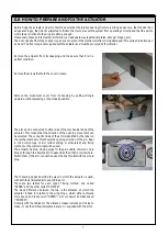
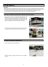
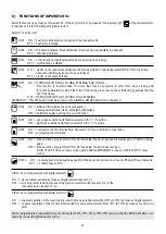
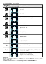
5) MANUAL FUNCTION SELECTORS

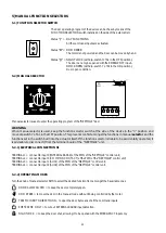
5.1) FUNCTION SELECTOR SWITCH


The door operating program of the device can be chose by means of the
FUNCTION SELECTION switch installed on the side of the automatism.

Status “

|

”  = 

DAY FUNCTIONS


All the command inputs are activated.

Status “

O

” =

DOOR FREE

.

                                                                   The motor is not powered and the door can be moved by hand.

                                                Status “

||

” = 

NIGHT LOCK

 (with dip-switch 7 of S1 in the OFF position).

                                                                   The door can only be opened with the EMERGENCY input..
                                                                  

DOOR OPEN

 (with dip-switch  7 of S1 in the ON position).

                                                                   Door open condition.

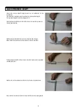
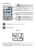
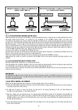
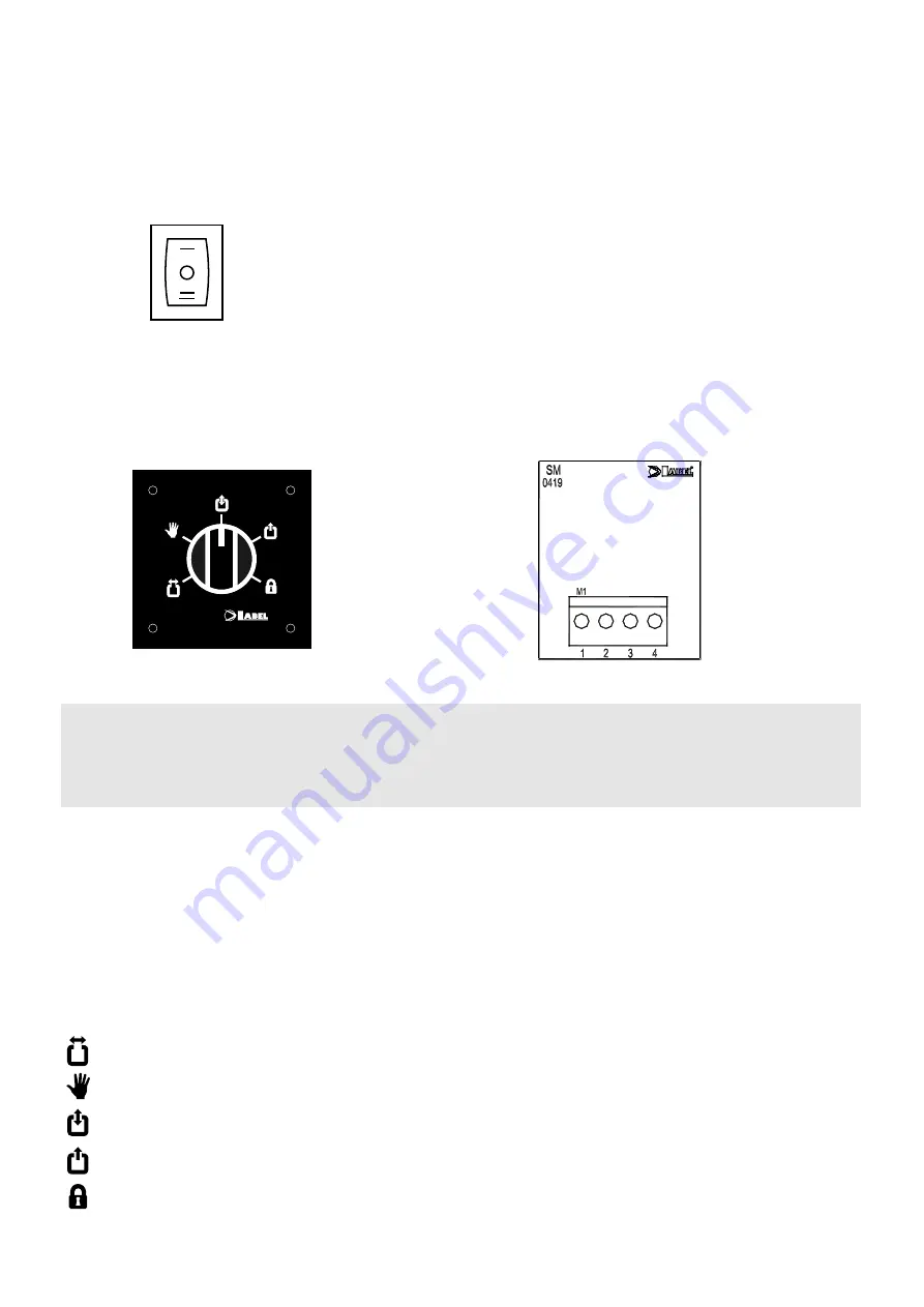
5.2) MANUAL SELECTOR


Manual selector is used to enter the operating program of the "NEPTIS/LE” door.

WARNING

When manual selector is used, keep the function selector switch at the side of the device in the “0” position and 
move dip switch 7 of S1 in the OFF position. This prevents conflict amongst the functions in manual 

selector 

and the 

functions set in the switch built into the actuator itself. If the function selector is liable to be accidentally operated, it 
is advisable to disconnect it from the terminal board of the  "NEPTIS/LE” unit.

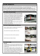
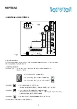
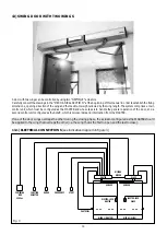
5.2.1) ELECTRICAL CONNECTIONSI

TERMINAL 1 = connect to input 9 (INTERNAL RADAR) of the PWN of the "NEPTIS/LE” control unit;
TERMINAL 2 = connect to input 3 (COMMON CONTACT) of the PWN of the "NEPTIS/LE” control unit;
TERMINAL 3 = connect to input 1 (AUX1) of the PWN of the "NEPTIS/LE” control unit;
TERMINAL 4 = connect to input 4 (AUX2) of the PWN of the "NEPTIS/LE” control unit.

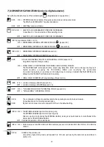
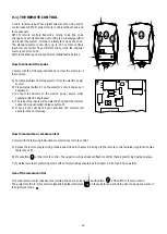
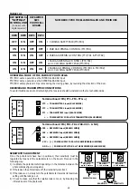
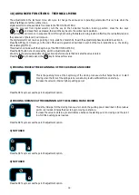
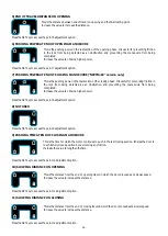
5.2.2) OPERATING MODES

Turn the knob of manual selector SMN to select the desired function from amongst the 5 available ones

         DOOR ALWAYS OPEN = to keep the door completely open.

         DOOR FREE = to move the door in the manual mode without it being controlled by the motor.

         TRAFFIC IN BOTH DIRECTIONS = to open the door by means of all the command inputs.

         EXIT TRAFFIC ONLY = to cut out  EXTERNAL RADAR input detection.

         NIGHT LOCK  = to keep the door shut, allowing it to be opened with the EMERGENCY input only.


21

Neptis

Summary of Contents for NEPTIS/LE

Page 1: ...Installation Manual SWING DOOR OPERATOR for one or two wings GB Nepti N e p t i S CD0356GB NEPTIS LE Rel 1 0 03 2007 NEPTIS LE ...

Page 2: ...37 EC and that it conforms to the essential safety requirements of the following directives Low Voltage Directive 73 23 EEC and successive modification 93 68 EEC Electromagnetic compatibility Directive 89 336 EEC and successive modifications 92 31 EEC and 93 68 EEC LABEL S p A Sede ITALY 43100 PARMA S Pancrazio P se Via Ilariuzzi 17 A Tel 39 0521 6752 Fax 39 0521 675222 infocom labelspa it web www...

Page 3: ... OF DIP SWITCH S1 22 7 FUNCTIONS OF DIP SWITCH S2 only via digital selector 23 8 POTENTIOMETER ADJUSTMENTS 24 9 DIGITAL SELECTOR 25 9 1 THE REMOTE CONTROL 26 9 2 ADJUSTING THE DEVICE WITH REMOTE PROGRAMMING VIA SELECTOR 27 10 COURTESY MODE FOR THE DISABLED 28 11 ELECTRO LOCK RELEASE WITH FREE DOOR 28 12 PHOTOCELL BOARD 28 13 SWING DOOR WITH TWO WINGS 30 13 1 ELECTRICAL CONNECTIONS 30 13 1 1 ACTUAT...

Page 4: ...MECHANICAL SECTION NEPTIS LE 550 110 120 Nepti N e p t i S ...

Page 5: ...d housing 7 Projecting pin 8 Spring locking screw 1 0 ACTUATOR COMPONENTS 1 Regulating dip switches and potentiometers 2 Powering board and connections 3 Spring 4 Spring preload reference 2 0 ARMS ARTICULATED ARM 8 5 6 1 7 7 2 3 4 SLIDING ARM ...

Page 6: ...or damage deriving from unauthorized modifications to the system Only use genuine spare parts if replacements or repairs are required The manufacturer cannot be held liable for the way the doors or gates to be automated are constructed or for damages caused by failure to build the doors and gates in compliance with good workmanlike techniques Protection degree IP22 requires that the actuator only ...

Page 7: ...f the pin Bear in mind which type of arm either sliding or articulated and fixing method on the wall or wing will be used The actuator has two closing plugs for the pin outlets of which one is broken through to allow the pin to pass while the other remains whole Switch them if the arm connection uses the shaft outlet with the whole plug Remove the aluminium cover from its housing by pulling strong...

Page 8: ...ght with different fixing sizes 1 1 Fixing drawings available on request 0 500 1000 1500 mm 50 100 120 150 Kg 0 250 mm 261 220 B A C B C A X 12 5 mm X 36 5 mm X 60 5 mm standard X 84 5 mm 261 69 115 115 123 23 123 106 546 261 6 220 50 37 X 18 5 12 ARTICULATE PUSH ARM 7 0 TECHNICAL DRAWINGS ...

Page 9: ...5 115 123 123 106 546 23 261 20 5 0 200 261 18 5 12 X SLIDE PULL ARM 1 0 500 1000 1500 mm 50 100 120 150 Kg 1 NOT Utilizable Length and weight Utilizable Length and weight Utilizable Length and weight with different fixing sizes Fixing drawings available on request 9 mm ...

Page 10: ...ring the closing phase can be selected in the following way Connect the arm to the output shaft with the wing fully open so as to load the spring to the minimum Connect the arm to the output shaft with the wing fully closed so as to load the spring to the maximum Connection in an intermediate position loads the spring to a proportionally intermediate value Make sure that the puller nut screwed int...

Page 11: ...re the standard preload and lock the spring Before you remove the arm you must restore the spring load to its standard value whereby the red mark on the belt matches the red mark on the pulley see figure alongside and lock the spring in this position To do this move the door by hand until this condition has been obtained and the red marks on the belt and pulley match Move the locking screw from th...

Page 12: ...econnect the arm from the conical connection by unscrew the two head screws Set the extension shaft in the conical connection like in figure Remember to keep the main screw inside conical connection Fix the extension shaft on the conical connection by two screw supplied with the extension Set the arm on the extension and fix to it by the two original screws About arm connection and arm removal ref...

Page 13: ...nt Check wiring connections Check that arm connection screw are well tightened Check that door leaf are stable and the movement is steady without friction from full open to full close position Check the condition of the hinges and lubricate it Check that speeds timing and safety functions are well adjust Check that safety and activation sensor are properly functioning Attention Any part that appea...

Page 14: ...notes ...

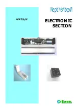
Page 15: ...ELECTRONIC SECTION NEPTIS LE Nepti N e p t i S ...

Page 16: ...terminal 3 contact made in position on the AUX1 terminal contact made in position on the AUX2 terminal Terminals 2 3 N C input of the safety PHOTOCELL Activates during the closing phase and reverses the door s direction Terminals 5 7 N C input of the opening safety SENSOR mod SSS1 The door stops if an obstruction or person is detected and only starts opening again when the sensor has been released...

Page 17: ...Terminal 13 DATA ITEM Terminal 14 12 Vdc powering positive Terminal 15 G ground Use the 4 pin terminal board in the selector kit WARNING The selector kit includes the LOGIC TAST interface board which must be fitted into connector J8 see fig 2 so as to allow the selector to work with the NEPTIS LE control unit TERMINAL BOARDS M5 M6 Dedicated to connection of photocell PRJ38 capsules see sect 12 for...

Page 18: ...STER SLAVE wiring for NEPTIS LE mod WR3MS CONNECTOR J8 connection for the LOGIC TAST interface module of selector CONNECTOR J9 connector for the photocell board Dip switch S1 selects the operating programs of the control unit see sect 6 Potentiometer calibration of the operating parameters see sect 8 Buzzer horn MP1 microprocessor with label indicating the software version BRIDGE J12 it selects th...

Page 19: ...off the mains power supply 230V for about 5 seconds i Turn on the mains power again and wait for an acoustic signal BEEP j Set dip switch 6 of Minidip S1 to the OFF position k Switch off the mains power supply 230V for about 5 seconds l Turn on the mains power again and wait for an acoustic signal BEEP m Press button PS1 START on board PWN The control unit will issue 5 beeps and will begin the spr...

Page 20: ...uvring area and the door must not be helped along by hand Once the initial set up has terminated make an opening manoeuvre by means of a command input and check the movements according to the default settings SAFETY The thrusting force of the door can be checked during the starting phase and at various stages of its movement by listening to the buzzer and the indications given by the warning light...

Page 21: ...unctions set in the switch built into the actuator itself If the function selector is liable to be accidentally operated it is advisable to disconnect it from the terminal board of the NEPTIS LE unit 5 2 1 ELECTRICAL CONNECTIONSI TERMINAL 1 connect to input 9 INTERNAL RADAR of the PWN of the NEPTIS LE control unit TERMINAL 2 connect to input 3 COMMON CONTACT of the PWN of the NEPTIS LE control uni...

Page 22: ...n with function selector in the position OFF night lock condition with function selector in the position DIP 8 ON courtesy function for the disabled See section 10 for a description of operation OFF courtesy function inhibited DIP 9 ON if the operation program NIGHT LOCK is selected the door opens and remains open 10 before closing again OFF if the operation program NIGHT LOCK is selected the door...

Page 23: ...U and modifying the parameters in points 13 wing delay on opening and 14 wing delay on closing Consider that the MASTER unit is delayed while the SLAVE unit is delayed on opening OFF WING DELAY INHIBITED with wings starting at the same time DIP6 ON control unit set up as SLAVE see sect 13 OFF control unit set up as MASTER see sect 13 DIP7 ON DOUBLE WING DOOR OPERATING MODE see sect 13 OFF SINGLE W...

Page 24: ...sity Push Go activating distance Intensity of final thrust in last closing section to make it easier to fit into electro lock Power of 0 5 sec stroke on closing before opening to release electro lock At the minimum value the closing stroke is inhibited and the electro lock is activated at the same time as the motor starts Remote control auto learning memorizing Push the button on the remote contro...

Page 25: ...e moved by hand Press the key green led on to inhibit the stepping function activated by dip switch DIP 1 of S2 9 DIGITAL SELECTOR The package with digital selector also contains the LOGIC TAST electronic board which is the interface module required for exchanging data between digital selector and the electronic control unit The LOGIC TAST board must be fitted into connector J8 of the LGN part of ...

Page 26: ...r to the electric power source while keeping button P1 depressed D The leds of the inputs will now start to show that the memory cells are being cancelled Release button P1 E Once all the cells have been cancelled the selector will operate in the normal way 2 1 2 3 4 P1 How to memorize a remote control Comply with the following instructions to memorize a remote control A Access the remote programm...

Page 27: ... on O Repeat the operations as given for MINIDIP S1 to select and change the status of the individual DIP SWITCHES P Press the SET button to move to POTENTIOMETER TM1 The 2 WAY traffic led will come onI Q When the potentiometers are being used the input leds form a scale to indicate the set value R To change the value of the selected potentiometer press R1 the DOOR FREE button to decrease the valu...

Page 28: ...he door for being opened when pushed by hand the next time Use digital selector and press key green led on to automatically release the electro lock at the end of each door closing phase in all the day functions Press key green led off to inhibit the option WARNING It is inadvisable to activate the function DIP 2 S2 ON by using manual selector as a variation in the door s operating program can lea...

Page 29: ...he potentiometer depending on the distance between the photocells see figure alongside 2 If the leds on the phtocells are off their sensitivity is correct 3 If the leds are on slowly turn the potentiometer towards its maximum setting until the leds go out 4 Check to make sure that the relative leds come on by breaking the infrared beam of the photocells MIN POTENTIOM SETTING up to 2 meters POTENTI...

Page 30: ...nsions opening direction of the wing and the maximum weight allowed by the wing length The system comprises a main control unit which must be configured as the MASTER and whose task is to handle the general operation of the door and a second control unit configured as the SLAVE which receives orders and information from the MASTER If one of the door wings overlaps the other during the closing phas...

Page 31: ...n 9 must be connected to the MASTER control unit so that the required operating program can be selected 13 1 2 ACTUATOR WITH SLAVE CONTROL UNIT Power the SLAVE control unit at 230V a c via terminal board M1 Opening safety sensor mod SSS1 installed on the wing controlled by the SLAVE actuator must be connected between terminals 5 7 of the SLAVE control unit and will only influence the actions of th...

Page 32: ...t 6 7 and 8 Remember that some of the settings must only be made on the MASTER control unit while others must be made on both the MASTER and SLAVE Carefully consult the TABLE in sect 15 which shows for each parameter whether the adjustment concerns both the control units or just the MASTER If the door wings must be delayed on starting set potentiometer TM2 closing speed of the MASTER control unit ...

Page 33: ...PUTS DIP 11 RESETTING OF TECHNICAL MENU DEFAULT VALUES see TECHNICAL MENU DIP 12 CONTROL UNIT RESET 33 14 PEDESTRIAN OPENING The pedestrian opening function can only be used for a swing door with two wings It is therefore essential for the actuators to be set up for operation as a DOUBLE WING DOOR see sect 13 To enable the PEDESTRIAN OPENING function set dipswitch 4 of S2 ON and select the conditi...

Page 34: ...INK ELECTRO LOCK TM10 POWER OF CLOSING STROKE FOR RELEASING ELECTRO LOCK 16 MEANINGS OF THE BUZZER SIGNALS BEEPS 5 BEEPS control unit without initial set up press START with function selector switch in 0 position Long BEEP control unit without initial set up keeping START depressed with function selector switch on I or II 6 BEEPS ENCODER not operating or disconnected 1 BEEP programming procedure a...

Page 35: ...e TECHNICAL MENU Press the SET button once to access the point 1 adjustment option simularly to the previous adjustments the yellow leds form a scale that indicates the value entered Press the key to decrease or the key to increase this value 1 PUSHING FORCE AT THE BEGINNING OF THE CLOSING MANOEUVRE Press the SET key to access the point 2 adjustment option 2 PUSHING DISTANCE AT THE BEGINNING OF TH...

Page 36: ...om being detected as an obstruction and preventing the manoeuvre from being completed Increase the value to obtain a higher power This is the pushing power in the last section of the closing phase It is useful for preventing friction in the lock from being detected as an obstruction and preventing the manoeuvre from being completed Increase the value to obtain a higher power This is the time for w...

Page 37: ...ribed below A access the programming mode by means of the selector B set dip switch 11 of switch S2 to the on position following the procedure described in sect 9 2 C quit the programming mode and memorize the data The control unit will issue 2 bips to indicate that the default values have been activated again This parameter can only be adjusted after the DOUBLE WING DOOR dip 7 of dip switch S2 ON...

Page 38: ...notes ...

Page 39: ......

Page 40: ...a Ilariuzzi 17 A Tel 39 05 21 67 52 Fax 39 05 21 67 52 22 e mail infocom labelspa it http www labelspa it S Pancrazio P se 43100 PARMA ITALIA S p A Made in Italy by AZIENDA CERTIFICATA SISTEMA QUALITA UNI EN ISO 9001 2000 ...

Reviews: