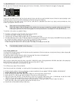
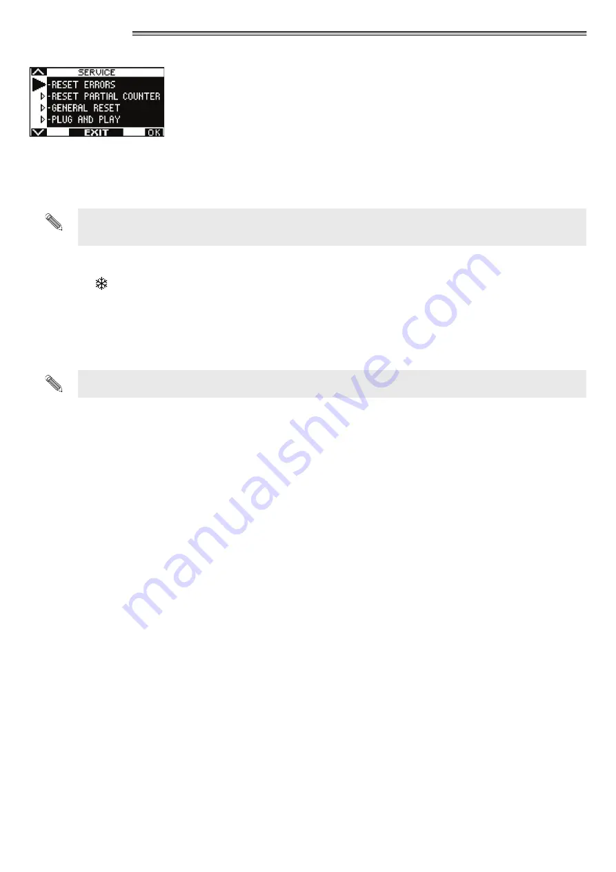
background image

47

19) MAINTENANCE

To enter, type the 10-character technical password (for more information, refer to the “Password management” paragraph).

This section is accessed only to reset any fault existing in the events memory and the partial counter of the door opening/closing cycles 

performed by the door and to reset the initial setup carried out during commissioning.

The  event  memory  and  partial  counter  reset  must  be  performed  by  specialized  personnel  only  during  routine  maintenance,  after 

performing all system operation checks.

Never erase the setup ("General Reset").

Only in the cases of leaf run change or arm removal it is necessary to erase the setup and proceed with a new setup 

following the operations described in paragraph 10.3 (for single leaf door) or in paragraph 21.2 (for dual leaf door).

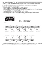
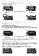
The buttons in this section are used as follows:

• 

The button ν 


allows moving forward in the reset type selection.

• 

The button ^ 

F2

 allows returning to the previous reset.

• 

The button 

F1

 (OK) allows confirming data reset for the selected reset type.

• 

The button 

F3

 is used only in case of dual leaf swing door and symbol on the top right on the display indicates 

M

 if the reset operations 

are related to the Master automation, or 

S

 if they are related to the Slave automation.

Each pulse on the button 

F3

 allows switching from 

M

 to 

S

 and vice versa.

In case of single leaf automation, on the top right of the display it is displayed the letter 

M

.

The GENERAL RESET clears the setup.
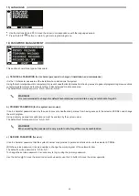
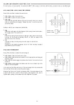
19.1) PLUG AND PLAY

The Plug and Play option allows to set the functions and the parameters of the automatic door directly at the factory, before shipping the 

automation to the installation site.

To adjust the functions and parameters, refer to the paragraph "Functions and Adjustments".

“PLUG and PLAY” only works for single-leaf swing doors.

It cannot be used for dual‑leaf doors.

After you have selected the desired functions, access the "SERVICE" section of the digital selector ET-DSEL described in this paragraph, 

select with the arrow the option "PLUG and PLAY" and press the button F1 (OK). 

The buzzer of the electronic control unit emits 5 beeps.

Turn off the power supply of the automation.

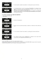
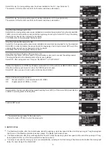
Once the automatic door is installed, in order to perform the initial setup, follow the procedure below:

a)  The first step to perform is the spring charging procedure described in the paragraph "SPRING LOADING PROCEDURE".

b) 

MOVE THE DOOR TO CLOSED POSITION.

c)  Power the automation NEXT 120S with mains voltage, the control unit buzzer emits 5 beeps.

d)  Select position "

I

" on the manual selector located on the side cap of the automation.

e)  Press the button PS1 (START) on the electronic control unit to start the initial setup cycle, or alternatively, access the section 

"SETUP" of the general programming menu and select the option "PARTIAL" as setup mode.

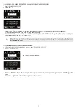
f)  During the setup cycle, the door moves slowly from closed position to fully open position, in order to learn the leaf run.

  At the end of the cycle a prolonged beep signals that the setup is over.

g)  Now the door will operate according to the setup.

Summary of Contents for NEXT 120s

Page 1: ...INSTALLATION MANUAL NEXT 120S EN Rel 1 2 02 2021 CD0752EN NEXT 120S Automation for automatic swing doors English TRANSLATION OF THE ORIGINAL INSTRUCTIONS EN ...

Page 2: ......

Page 3: ...OGRAM SELECTOR 27 12 BATTERY PACK NEXT BAT120S 29 13 GENERAL PROGRAMMING MENU 30 14 FUNCTIONS AND SETTINGS 31 14 1 FUNCTIONS SETTING 31 14 2 POTENTIOMETER ADJUSTMENT 31 15 LANGUAGE 39 16 PASSWORD MANAGEMENT 39 16 1 HOW TO CHANGE THE TECHNICAL PASSWORD 40 16 2 HOW TO CHANGE THE PRIMARY PASSWORD 40 16 3 HOW TO CHANGE THE SERVICE PASSWORD 41 16 4 ENABLING USER PASSWORD USAGE PRIMARY AND SERVICE 42 16...

Page 4: ...t be installed in explosive environments or atmospheres or in the presence of flammable gases or fumes Make sure that the characteristics of the electric distribution network are compatible with the technical data indicated in this manual and that upstream of the system there is an omnipolar switch with an opening distance of the contacts of at least 3mm and a residual current device The automatic...

Page 5: ... type of arm they include the application design with installation dimensions and the chart that depending on the automation model provides the weight limits based on the length of the door leaf The technical data provided in the drawings refers to a typical installation but may be influenced by variables inherent to each closing such as friction environmental conditions alignment of the leaf hing...

Page 6: ...ure of the automation should be firm with no significant deformation The structure of the leaf must be rigid and strong The leaf hinges must be adequate and in good condition The length and weight of the leaf must be within the operating limits of the automation The movement of the leaf must be smooth and free of friction throughout the run The door requires mechanical stops consisting of a mechan...

Page 7: ...Pull the cover out of its housing by releasing it at its ends and pulling it upwards fig 1 Remove the plastic side caps from the plate by loosening the socket head cap screws M5x8 fig 2 Remove the enclosure of the electronic control unit from the plate by unscrewing the two countersunk hex head screws M5x8 fig 3 Remove the motor spring mechanic unit from the plate by unscrewing the two socket head...

Page 8: ...alling the automation NEXT 120S the spring loading procedure must be performed before inserting the arm pin into the shaft output of the automation 5 4 SPRING LOADING PROCEDURE Carefully follow the following steps to load the spring of the automation NEXT 120S a make sure that the arm is not inserted into the automation b Select position II on the manual selector located on the side cap of the aut...

Page 9: ...ill emit 5 beeps and the gearmotor will perform a slow rotation of one turn in the direction of the arrow Once the maximum spring load position has been reached the motor will stop and some beeps will sound Release the button PS1 WARNING DO NOT REMOVE 230V POWER TO PREVENT SPRING UNLOAD d Now insert the arm pin into the shaft output of the automation ensuring that the plastic plate is clipped onto...

Page 10: ...10 X 51mm X mm 6 TECHNICAL DRAWINGS 6 1 SLIDING PULL ARM NEXT120 BDT STANDARD TAPERED PIN NEXT EXT EXTENSION TAPERED PIN ...

Page 11: ...11 X 36mm X 6 mm 6 2 SLIDING PUSH ARM NEXT120 BDS STANDARD TAPERED PIN NEXT EXT EXTENSION TAPERED PIN ...

Page 12: ...12 x X 36mm X 6 mm 6 3 ARTICULATED PUSH ARM NEXT120 BAS STANDARD TAPERED PIN NEXT EXT EXTENSION TAPERED PIN ...

Page 13: ...13 X 91mm X mm 6 4 ELBOW SLIDING PULL ARM NEXT120 B150 STANDARD TAPERED PIN NEXT EXT EXTENSION TAPERED PIN ...

Page 14: ...14 X 91mm X mm 6 5 ELBOW SLIDING PULL ARM NEXT120 B250 STANDARD TAPERED PIN NEXT EXT EXTENSION TAPERED PIN ...

Page 15: ...20 BAS LEAF MOUNTING 6 7 SHAFT EXTENSION PIVOT NEXT EXT NEXT EXT Shaft extension pivot 25mm Applicable on all types of arms to increase the distance between automation and arm STANDARD TAPERED PIN NEXT EXT EXTENSION TAPERED PIN ...

Page 16: ...ening distance of at least 3 mm Use self extinguishing cables for electrical connections Separate the mains power supply line from the very low voltage line control unit relative to control and safety accessories On the plastic side caps of the automation NEXT 120S there are the holes that must be broken open through which the electric cables must be inserted The installer must take care to secure...

Page 17: ...LECTOR 0 0 24 24V 24 24V INTERNAL RADAR EXTERNAL RADAR COMMON 0 AUX1 COMMON AUX2 OPEN 3 CLOSING SIDE SENSOR SWITCH B4 ON OPENING SIDE SENSOR SWITCH A7 ON SWITCH B4 OFF COMMUNICATION CABLE OA EDGET SAFETY SENSORS OUTPUTS MAIN SENSOR SECONDARY SENSOR CLOSING SIDE OPENING SIDE POWER TEST PURPLE SEN CL 7 COMMON 0 SEN OP 6 COMMON 0 0 GND YELLOW GREEN GREY DO NOT CONNECT BLUE PINK BLACK T TEST BROWN 0 W...

Page 18: ...EP 3 Separate view of the parts Connection to the power supply terminal Insertion of wired terminal into the protective enclosure STEP 4 STEP 5 Closing of the protective enclosure Plug in connection to the 230V input connector of the control unit of NEXT 120S ...

Page 19: ...afety sensor N C contact Terminals 0 7 input of closing safety sensor N C contact Terminals 0 24 24Vdc output 0 negative 24V positive Terminals 0 T Test for safety sensors 0 negative T positive Terminals S 24V Open Collector output The mode of operation depends on the multi function F41m Terminals C NO NC Common normally open normally closed Potential free contact of relay RL1 to connect the elect...

Page 20: ...E T PARAMETERS ON DIGITAL SELECTOR ET DSEL A7 ON Low level test input A8 OFF Input test delay 10msec B4 OFF Sensor installed on opening side B4 ON Sensor installed on closing side F11 S05 ON Closing safety sensor F12 S06 ON Opening safety sensor F13 S07 ON TEST of opening safety sensor F14 S08 ON TEST of opening safety sensor F15 S09 OFF Test level LOW 8 2 FLAT SCAN SAFETY SENSOR CONNECTION OF FLA...

Page 21: ...ser but only to select the operating mode of the automatic door the user can also select the preferred language and set up a user password to prevent the use of the digital selector by unauthorized persons Connect the digital selector ET DSEL to the control unit of the automation NEXT L120S using a 0 33mm 4 wire twisted pair cable for RS485 applications Terminal 13V connect to the terminal of the ...

Page 22: ...l leaf automatic door refer to the paragraph Dual leaf door Follow chapter 10 1 only if the digital selector ET DSEL is new and is powered on for the first time Follow chapter 10 2 if the digital selector has already been used before 10 1 FIRST START OF THE DIGITAL SELECTOR ET DSEL Power the automation NEXT 120S with mains voltage the control unit buzzer emits a few quick short beeps Language sele...

Page 23: ...L is A A A A A A A A A A Press the button in correspondence with letter A an asterisk appears on the position of the first letter repeat this operation for all the other characters required If the password you entered is correct you enter the configuration section of the setup if the password you entered is incorrect you are returned to the general programming menu It is advisable to change the te...

Page 24: ...tion control unit to monitor the safety sensors The setup depends on the characteristics of the sensor installed Select OFF when using sensors of the type OA EDGE T or FLAT SCAN Contact configuration on OPEN input between terminals 0 3 of the control unit NEXT L120S Select ON with a normally open contact or when the OPEN input is not used Select OFF when you use a device with a normally closed con...

Page 25: ...noise signal when the power limit is reached set the F49 function to ON see Functions setup The buzzer noise for almost the entire run means that the leaf exceeds the limits allowed or that the installation dimensions indicated in the assembly technical drawings were not respected or that frictions exist on the door in this case the movements of the automatic door are not smooth and the opening cl...

Page 26: ...lector from the terminal box of the control unit NEXT L120S if you have installed the mechanical selector EV MSEL ELECTRIC CONNECTIONS Terminal 1 of EV MSEL to terminal 2 Internal radar of the control unit NEXT L120S Terminal 2 of EV MSEL to terminal 0 Common of the control unit NEXT L120S Terminal 3 of EV MSEL to terminal 5 AUX 1 of the control unit NEXT L120S Terminal 4 of EV MSEL to terminal 4 ...

Page 27: ...e opening Manual free door Automatic operation is disabled and the door can be opened manually Automatic bidirectional program The door automatically opens after an opening command Automatic unidirectional entry only program To disable exit detection on internal Radar input Night lock program The door can only be opened by the OPEN input or by radio control if the radio receiver is installed Power...

Page 28: ...e button F1 to open the door but only in bi directional and unidirectional programs if function F32 OFF Press F1 to open the door in all operating programs both automatic and night lock if function F32 ON F3 It is used only in a MASTER SLAVE double leaf door automation In the main screen of the work program the button F3 has no operating function Its function is just to toggle from MASTER to SLAVE...

Page 29: ...EXT 120S to keep operating Battery life depends on several factors such as the number of operations carried out the weight of the leaves the external devices connected etc The charged battery can supply energy for approximately 1 hour with continuous door opening closing cycles IMPORTANT BATTERY TYPE NiMH 19 2V 600mAh LED SIGNALLING SIGNALLED EVENTS GREEN LED DL6 RED LED DL5 BATTERY DISCONNECTED O...

Page 30: ...r the selected sub menu press briefly the ENTER button To exit the general programming menu and return to the work program view press the EXIT button DIAGRAM 1 INITIAL SETUP SECTION SERIAL COMMUNICATION SETUP SECTION FUNCTIONS AND SETTINGS SECTION PASSWORD MANAGEMENT SECTION SELECTOR OPTION SECTION LANGUAGE SECTION MAINTENANCE SECTION If you enter the initial setup section see paragraph 10 3 If yo...

Page 31: ...isplayed the letter M button to return to the general programming menu 14 1 FUNCTIONS SETTING In this section the display describes the purpose of the selected function the button F1 sets the function status to OFF the button F3 sets the function status to ON the button F2 allows to go to the next function the button allows returning to the previous function For information about the operation of ...

Page 32: ...al program selector in position II selection of the work program night lock ON Operating mode of manual program selector in position II selection of the work program open door F071 OFF Battery module not installed S ON Battery module NEXT BAT120S installed F08 OFF Operation with battery in the absence of mains power supply the door continues to operate normally ON Operation with battery in the abs...

Page 33: ...automatically closes if the closing command is not given within 30 seconds F20 OFF Standard operation on the internal and external radar inputs ON Operation with separate opening and closing commands The external radar input controls the opening the internal radar input controls the closing without automatic closing The OPEN input operates in standard mode F211 OFF OPEN input configuration normall...

Page 34: ...e leaf door after a power failure during the first opening movement the leaves start at the same time ON For double leaf door after a power failure during the first opening movement the leaves start respecting the offset F36m Multiple selection function Multiple selection function allowing to set the position of the manual or mechanic program selector where the pedestrian opening function of only ...

Page 35: ...ive Please check paragraph PRIVACY FUNCTION F78 Function active if F77 ON OFF for maglock without status sensor open closed factory setting The operator NEXT 120S is automatically detecting the close door status ON Read this function just in case you install a maglock with status sensor open closed not supplied by Label for maglock with status sensor open close Connect the N O output contact of th...

Page 36: ...sing the value increases the degrees of leaf motion required before starting the opening Adjustment between 2 and 15 S P09 Potentiometer enabled if F02 ON and F03 OFF Final push for electric lock engagement Increasing the value increases the leaf speed in the last degrees of the closing movement to ease the engagement of the electric lock S P10 Potentiometer enabled if F02 ON Closing thrust to rel...

Page 37: ...S P25 Intensity of door braking at the end of the opening after a manual push Increasing the value increases the leaf braking S P26 Distance from the end of the run during opening starting from which it is braked after a manual push Increasing the value increases the distance from the final ledge in opening where the door is braked during the manual push S P27 Leaf braking intensity when the openi...

Page 38: ...r locked until the user activates the internal touchless sensor to open the door and exit From value 1 to 100 time is set from 1 to 100 minutes Once this time period is expired the traffic light flashes red green advising the user that door will be unlocked within 3 minutes P36 Not used P37 Not used P38 Not used P39 Not used P40 Not used P41 Not used P42 Not used P43 Slowdown ramp during opening I...

Page 39: ...password and to be very careful not to forget it b PRIMARY PASSWORD for the system owner user It is a 5 character password used by the user to prevent unauthorized persons from having access to the selector ET DSEL and change the work program Using a primary password is optional and must be enabled by the system owner The default technical password is A A A A A WARNING When enabling the password b...

Page 40: ... 2 HOW TO CHANGE THE PRIMARY PASSWORD Select PRIMARY PASSWORD Press OK F1 Type the default primary password A A A A A by pressing 5 times the button A If the primary password is not the default password since it had already been changed before enter the currently used primary password Enter the new primary password selecting a combination of 5 characters from the letters A B C D 16 1 HOW TO CHANGE...

Page 41: ...procedure Enter the primary password Enter the new service password selecting a combination of 5 characters from the letters A B C D You are prompted to repeat the new password so enter again the previous combination If the password entered is correct PASSWORD OK is displayed for one second and the system returns to the PASSWORD MANAGEMENT section 16 3 HOW TO CHANGE THE SERVICE PASSWORD Select SER...

Page 42: ... user decides to enable password usage it is recommended to change the combination of both primary and service password 16 5 DISABLING USER PASSWORD USAGE From the PASSWORD MANAGEMENT section select PASSWORD ON OFF Press the button OK F1 Enter the primary password Press the OFF button F1 to disable user password usage To return to the general programming menu press the EXIT button twice Access to ...

Page 43: ...to use Bidirectional program The buttons in this submenu are used as follows The button allows going to the next function The button F2 allows returning to the previous function The button F1 sets the function status to OFF The button F3 sets the function status to ON Exit Only Program Entry Only Program Open Door Program Night Lock Program Manual Free Door Program Pedestrian Opening For Dual Leaf...

Page 44: ...information of the Slave automation Each pulse on the button F3 allows switching from M to S and vice versa In case of single leaf automation on the top right of the display it is displayed the letter M The button F1 allows to go to the event memory to display fault messages press it again to return to the information area The button EXIT allows returning to the main display of the work program of...

Page 45: ...utomation I5 Version of microcontroller B Displays the software release of the microcontroller B of the logic board NEXT L120S of the automation I6 Identification number Identification number including data for manufacturer use The events memory stores the last 5 fault messages in chronological order When all the 5 memory cells include messages the subsequent event will be saved in cell E1 the oth...

Page 46: ... necessary to turn off the 230V power supply then turn it on again after a few seconds Check that the motor is running that the motor connector is properly plugged in and that the motor cables are not damaged 37 SAFETY SENSOR FAULT DURING OPENING Failed opening safety sensor test Check that the test settings and parameters are correct that the test has been enabled also on the safety sensor and th...

Page 47: ...e letter M The GENERAL RESET clears the setup 19 1 PLUG AND PLAY The Plug and Play option allows to set the functions and the parameters of the automatic door directly at the factory before shipping the automation to the installation site To adjust the functions and parameters refer to the paragraph Functions and Adjustments PLUG and PLAY only works for single leaf swing doors It cannot be used fo...

Page 48: ...is disabled from 01 to 100 the power of the thrust increases proportionally P11 introduces a delay in leaf opening start with respect to electric lock activation At value 0 the function is disabled from 01 to 100 the delay increases proportionally up to 4 seconds 20 2 ELECTROMAGNET Setup of the functions to enable the electromagnet F02 ON to enable the electric lock output F03 ON to enable permane...

Page 49: ...ock must be connected to the Master automation The safety sensors installed on the master leaf must be connected to the Master automation the safety sensors installed on the slave leaf must be connected to the Slave automation If the door is equipped with dual electric lock to lock individually each leaf connect to the Slave automation the electric lock which locks the Slave leaf The Master and Sl...

Page 50: ...raph 13 Enter the 10 character technical password to access setup for information about the use of the technical password refer to the paragraph Password management 16 and 16 1 BEFORE STARTING THE SETUP MOVE THE DOOR TO CLOSED POSITION FULL SETUP mandatory for the first installation of the automation PARTIAL SETUP to repeat leaf run learning if the mechanical limit stops are moved without modifyin...

Page 51: ...he safety sensors The setup depends on the characteristics of the sensor installed Select OFF when using sensors of the type OA EDGE T or FLAT SCAN Contact configuration on OPEN input between terminals 0 3 of the control unit NEXT L120S Select ON with a normally open contact or when the OPEN input is not used Select OFF when you use a device with a normally closed contact Choice of the work progra...

Page 52: ...low speed and you can choose with the function F35 if both leaves must start together or one after the other respecting the leaf delay F35 OFF In the first opening cycle the leaves start together F35 ON In the first opening cycle the leaves start one after the other respecting the leaf delay To set up the available functions refer to Functions setup paragraph To adjust the variable parameters refe...

Page 53: ...play On the top right of the display appears the letter M if the information is related to the Master operation the letter S if it is related to the Slave automation button F3 toggles from Master to Slave Master automation Slave automation In a swing door with two leaves reset the events memory on the SLAVE S automation and then on the MASTER M automation To reset the events memory select RESET FA...

Page 54: ...ens the door in all the operating programs of the automation 5 RECEIVER MEMORY ERASURE Should it be necessary to erase all the transmitter codes saved in the memory of the receiver NEXT RX proceed as follows a Disconnect the cable from the receiver NEXT RX from the connector J4 of the logic card NEXT b Press and hold the button SW1 of the receiver and at the same time connect the cable of the rece...

Page 55: ... the OPEN input of the automation The disabled can also use the SPYCO radio control paired with the radio receiver NEXT RX Set the pause time parameter P05 so as to keep the door open for a sufficient time to allow the disabled to cross the door before automatic closing If at the end of the opening manoeuvre or during the pause time the closing safety sensor detects the presence of the disabled pe...

Page 56: ...nd allow the two doors to operate independently you need to connect an ON OFF switch in parallel between terminals 5 AUX1 and 0 Common of both control units of the automations This way when the switch contact is open the interlock is enabled while when the switch contact is closed the interlock is disabled and the two automatic doors can operate independently To enable interlocked operation you ne...

Page 57: ...t one if its radar is engaged The interlock operation includes the following steps a the person approaching from the outside activates the external radar of door 1 and door 1 opens b the person enters the internal area between the two doors c door 1 closes back after the pause time d the person must activate the internal radar of the second door to get door 2 to open e door 2 opens when door 1 has...

Page 58: ...tus free or busy inside or outside Please connect the traffic lights in parallel It is possible to choose between two different traffic lights item T LED or item V00175 E n 1 UR2 Relay Module to control the traffic lights F n 1 N C emergency push button to release the maglock from inside G n 1 ON OFF Key selector to release the maglock from outside in case of emergency 25 1 ELECTRICAL CONNECTIONS ...

Page 59: ...y setting The operator NEXT 120S is automatically detecting the close door status ON for maglock with status sensor open close Connect the N O output contact of the status sensor to the inputAUX1 on NEXT L120S ontrol unit in order to detect the close door status FUNCTION F79 OFF The traffic light D show steady green light during the door movement and until the locking impulse is given by the user ...

Page 60: ...7 MAINTENANCE PROGRAM To ensure that the automatic door keeps running safely over time it is recommended to carry out the maintenance operations once every 6 months The installer can set the number of opening closing cycles after which the message PROGRAMMED MAINTENANCE will appear on the display of the selector ET DSEL or T NFC potentiometer P48 Warning Before starting the operations on the autom...

Page 61: ...n NEXT 120S has been realized to be incorporated in a machinery or to be assembled with other devices to constitute a machinery covered by Machine Directive 2006 42 EC Harmonized European regulations applied EN 13849 1 EN 13849 2 automation in category 2 PL d EN 61000 6 2 EN 61000 6 3 EN 60335 2 103 EN16005 Also declares that it is not allowed the commissioning of the product indicated until the f...

Page 62: ...62 ...

Page 63: ...63 ...

Page 64: ...NEXT Made in Italy by S p A Via Ilariuzzi 17 A S Pancrazio P se 43126 PARMA ITALIA Tel 39 05 21 67 52 Fax 39 05 21 67 52 22 infocom labelspa it www labelspa com ...

Reviews: