background image

LM1012TTS Table-Top Label Applicator System                                  


USER'S MANUAL 

Made in the U.S.A. 

© 2022 LABELMILL 

01/01/2022  Model LM1012TTS 

Page 14 


OPTIONAL ELECTRONIC CLEAR LABEL DETECTOR (ECLD) 

 
Description    

The Z-Z-ELC300 Label Sensor uses capacitive technology to sense label edges for registration, counting, splice detection 
or other applications. Capacitive technology provides the fastest and most accurate edge detection method available. The 
Z-Z-ELC300 has an integral cable, and uses an M12 connector. 
 

Setup 

1.  Web must remain in contact with the base/mounting plate during operation.  
2.  Label must pass under the [-SENSOR-] indicator.  
3.  Small labels should be centered under the [-SENSOR-] indicator.  
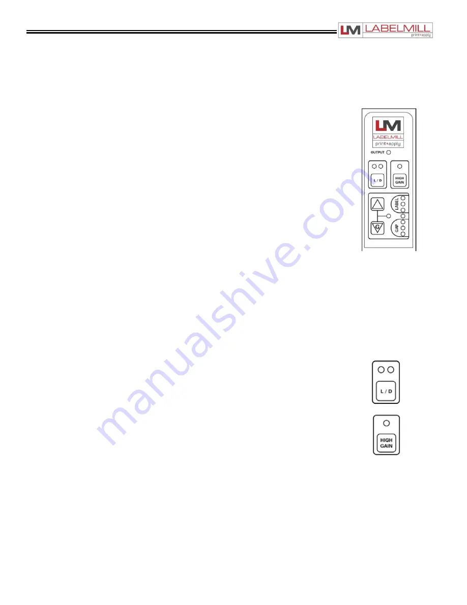
4.  When properly setup, the lights in the gray LABEL area will be on when a label is 

present, and lights in the gray GAP area will be on when a gap is present.   

5.  All lights flashing rapidly indicates over-current condition, likely caused by wiring error. 


AutoGap Setup


1.  Start with High Gain off.  
2.  Remove a label from the web.  
3.  Place the area of the missing label in the sensor (liner only).  
4.  Press  for at least 1 second (lights begin to move back and forth).  
5.  Release the button.  
6.  Setup complete.  
7.  Verify the light bar goes into the gray GAP area during gaps between labels and into the gray LABEL area 

during labels. If necessary, use arrow keys to adjust manually. If the light bar is not moving at least three or 
four lights, turn on High Gain. 


Manual Adjustment


When running, the light bar should extend from the gray LABEL area to the gray GAP area. The up and down arrows can 
be used to fine tune  the adjustment if necessary. If the adjustments reach the end of their range, the last light in the GAP 
or LABEL area will flash three times when the button is pressed. The light bar may move toward LABEL while the Up 
arrow is pressed. This is because the sensor body is deflecting and making the slot smaller.  It will return when the button 
is released and will  not affect setup. 
 

Sensor Configuration


Li

ght/Dark Switching In “Light” switching mode, the sensor outputs are active/on during the gap. In 

“Dark” 

switching mode, the sensor outputs are active/on during the label. Switch modes by pressing the 

button. 

Do not change while running. 


High Gain Mode


Only use High Gain mode when necessary. Very small or very thin labels may not consistently move 

the light 

bar between the LABEL and GAP areas. In this case, use the High Gain mode by pressing the 

button. 

Do not change while running. AutoGap must be performed after activating High Gain. 
 

Metal/Foil Label Setup


AutoGap Setup on a missing label area may not work reliably for rectangular metallic labels (foil  or metalized Mylar). In 
this case, place an actual gap in the sensor (use alignment groove on the sensor). Then hold the Gap button down for 
AutoGap as above. Move labels slowly through the sensor. Use manual adjustments if necessary to ensure the light bar 
is in the LABEL area during labels and GAP area during gaps. 


Summary of Contents for LM1012

Page 1: ...LM1012 TABLE TOP LABEL APPLICATOR SYSTEM OPERATIONS MANUAL Manufactured in USA by LabelMill Inc 2416 Jackson St Savanna IL 61074 800 273 4707 info labelmill com www labelmill com...

Page 2: ...3 PROGRAMMING CONTROL OPERATION System Controls Operator Interface 17 Control Accessory Connections 18 Programming 19 Quick Programming Flow Chart 22 Key Definitions 32 Set Up of Key Features 33 Input...

Page 3: ...bel Applicator System USER S MANUAL Made in the U S A 2022 LABELMILL 01 01 2022 Model LM1012TTS Page 3 SECTION 1 SYSTEM OVERVIEW Introduction 4 General System Specifications 5 Inventory List 6 User Re...

Page 4: ...ced label misplacement Heavy duty hybrid servo motor drive Hardened steel peeler plate for reduced wear Adjustable label sensor for expediting changeover without sacrificing accuracy The LM1012TTS wil...

Page 5: ...ion between labels in running direction LABEL SIZE Minimum 1 2 wide x 1 2 long Maximum 4 5 wide x 10 long LABEL PLACEMENT ACCURACY Up to 1 32 1mm when labels are produced to specifications and product...

Page 6: ...lar 1 12 Power Cord 1 Adjustable Electronic Label Sensor 1 Take Up Spool Clip 2 Module Mounting Knobs 1 Model LM1012 Operators Manual Optional Tamp Module LM1012TM QTY Description 1 Tamp Module Assemb...

Page 7: ...power and air controls at the source and lock out in accordance with OSHA Standards Be sure all external electrically conductive parts are connected to a good electrical ground Never handle live elect...

Page 8: ...2022 LABELMILL 01 01 2022 Model LM1012TTS Page 8 SECTION 2 SETUP OPERATION LM1012TTS Component Description 9 Web Routing 10 Label Sensor Adjustment 11 Label Sensor Calibration 12 Mechanical Label Det...

Page 9: ...LABELMILL 01 01 2022 Model LM1012TTS Page 9 COMPONENT DESCRIPTION Pinch Roller Release Knob Web Take Up Spool Lock Label Storage Spool Custom Product Fixture Spool Clip Pinch Roller Control Box Valve...

Page 10: ...eb take up spool F The take up spool rotates in a counter clockwise direction 7 Turn the Pinch Roller Knob G 180deg so that the pinch roller and drive roller contact each other When the roller is clos...

Page 11: ...100 label sensor must be set to the Clear setting in the Label Sensor menu LABEL PLACEMENT IN RELATION TO THE PEELER PLATE Loosen the lock screw on the photo eye rail assembly and slide it forward or...

Page 12: ...p flashing 3 The automatic setup is complete Steps 1 and 2 can be reversed Manual Sensitivity Adjustments The Teach Mode Setup should always be successful However the sensitivity can be adjusted manua...

Page 13: ...the edge of the label as it is fed When the star wheel catches the edge of the label the wheel will quit sliding and rotate The diameter across the flats of the star wheel is smaller than the diameter...

Page 14: ...at least three or four lights turn on High Gain Manual Adjustment When running the light bar should extend from the gray LABEL area to the gray GAP area The up and down arrows can be used to fine tune...

Page 15: ...M1012TTS Page 15 DRIVE MOTOR PACK To reduce waste web tension move the lock collar 1 32 away from the take up spool To increase web tension move the lock collar 1 32 toward the take up spool CAUTION T...

Page 16: ...LABELMILL 01 01 2022 Model LM1012TTS Page 16 SECTION 3 PROGRAMMING AND CONTROL OPERATION System Controls Operator Interface 17 Control Accessory Connections 18 System Programming 19 Programming Flow C...

Page 17: ...tor System USER S MANUAL Made in the U S A 2022 LABELMILL 01 01 2022 Model LM1012TTS Page 17 SYSTEM CONTROLS OPERATOR INTERFACE LCD DISPLAY OPERATOR KEYPAD INTERFACE ENTER PROGRAMMING MENU MANUAL TRIG...

Page 18: ...l LM1012TTS Page 18 ACCESSORY CONNECTIONS LOCATED ON BACK OF CONTROL BOX MAIN POWER POWER SWITCH MAIN DRIVE MOTOR EXTERNAL PRINTER INTERFACE START INPUT FUSE HEAD UP SWITCH SMART TAMP INPUT SOLENOIDS...

Page 19: ...SED TO 1 Enter and exit the program menu ENTER KEY IS USED TO 1 Access or Enter the selected PROGRAM BLOCK example TAMP SETUP 2 Access or Enter the data selection options line of the PROGRAM BLOCK Sub...

Page 20: ...leted Multiple Feed Programs how many system cycles occur with a single trigger signal Interval Delay Amount of time in seconds between multiple fed labels Note Active with quantity 2 TAMP SETUP This...

Page 21: ...nes the application type and sequence in relation to the label feed PROGRAMMABLE BLOCKS No Tamp Tamp Before Feed Tamp After Feed Blow Before Feed Blow After Feed Clam Shell Before Clam Shell After Rou...

Page 22: ...abel Applicator System USER S MANUAL Made in the U S A 2022 LABELMILL 01 01 2022 Model LM1012TTS Page 22 PROGRAMMING FLOW CHART LABELMILL MODEL LM1012TTS UP DOWN ARROW KEYS WILL SCROLL THROUGH THE PRO...

Page 23: ...LM1012TTS Table Top Label Applicator System USER S MANUAL Made in the U S A 2022 LABELMILL 01 01 2022 Model LM1012TTS Page 23...

Page 24: ...cator System USER S MANUAL Made in the U S A 2022 LABELMILL 01 01 2022 Model LM1012TTS Page 24 MAIN DISPLAYS Auto Setup is no longer used with the new style label sensor Do not use this feature with a...

Page 25: ...LM1012TTS Table Top Label Applicator System USER S MANUAL Made in the U S A 2022 LABELMILL 01 01 2022 Model LM1012TTS Page 25...

Page 26: ...LM1012TTS Table Top Label Applicator System USER S MANUAL Made in the U S A 2022 LABELMILL 01 01 2022 Model LM1012TTS Page 26...

Page 27: ...LM1012TTS Table Top Label Applicator System USER S MANUAL Made in the U S A 2022 LABELMILL 01 01 2022 Model LM1012TTS Page 27...

Page 28: ...LM1012TTS Table Top Label Applicator System USER S MANUAL Made in the U S A 2022 LABELMILL 01 01 2022 Model LM1012TTS Page 28...

Page 29: ...LM1012TTS Table Top Label Applicator System USER S MANUAL Made in the U S A 2022 LABELMILL 01 01 2022 Model LM1012TTS Page 29...

Page 30: ...LM1012TTS Table Top Label Applicator System USER S MANUAL Made in the U S A 2022 LABELMILL 01 01 2022 Model LM1012TTS Page 30...

Page 31: ...LM1012TTS Table Top Label Applicator System USER S MANUAL Made in the U S A 2022 LABELMILL 01 01 2022 Model LM1012TTS Page 31...

Page 32: ...e utilizes time the speed of the product MUST remain constant A product traveling at a higher velocity will travel further in a given time thus effecting the placement of the label QUICK START GENERAL...

Page 33: ...desired label speed 3 Manually move the label sensor to adjust the label stop position The proper stop position will be with the leading edge of the label stopping flush with the tip of the peeler pl...

Page 34: ...itch normally open is standard MENU TAMP SETUP 6 Set Label Speed to appropriate value MENU LABEL SPEED 7 Adjust position of Label Sensor so that label stops at edge of peeler plate BLOW SETUP Determin...

Page 35: ...OPTO INPUT WITH INTERNAL 24V COMMON OH HIGH CURRENT OUTPUT Rated 500ma All user inputs and outputs are SINKING type Example in order for a status light to illuminate for Run Status Ok the light should...

Page 36: ...p 4 Input X0 3 24v Common 5 24v Common 6 Shield SMART TAMP P2 PIN I O ADDRESS 24vdc 1 24vdc 2 2nd Trigger Pre Print AUX1 3 X0 1 Smart Tamp 4 X0 3 24v Common 5 24v Common 6 SHIELD SOLENOIDS P6 PIN I O...

Page 37: ...Applicator Busy 14 O Y1 2 Batch Done Aux Output 1 15 O Y1 6 Round Module Serial Plus Port DB9 Female P11 PIN INPUT OUTPUT ADDRESS SHIELD 1 485 RS232 XMIT port D to motor 2 485 RS232 RECV port D to mo...

Page 38: ...mp Applicator Module Installation 39 Tamp Module Setup 40 Flag Applicator Module Installation 41 Flag Module Setup 42 Round Product Applicator Module Installation 43 Round Product Applicator Module Se...

Page 39: ...s 6 Install the cable from the valve assembly into the connector on the accessory panel of the control box tagged SOLENOIDS if it is not already connected 7 Install the cable from the tamp module head...

Page 40: ...r plate P in the vertical position loosen the mounting screw M and adjust the vertical screws V in or out to achieve the 020 B NOTE The tamp pad T must maintain parallelism with the peeler plate P Air...

Page 41: ...the cable from the tamp module head up switch into the connector on the accessory panel of the control box tagged HEAD UP AUX 8 Install the six 6 airlines fitted with quick disconnect style fittings o...

Page 42: ...plate P in the vertical position loosen the mounting screw M and adjust the vertical screws V in or out to achieve the 020 B NOTE The label jaws J must maintain parallelism with the peeler plate P Ai...

Page 43: ...e from the valve assembly into the connector on the accessory panel of the control box tagged SOLENOIDS if it is not already connected 8 Install the cable from the round product module limit switch in...

Page 44: ...ed securely These supports D are moved to adjust for the size location and height of the product in relation to the label application roller Q 2 Thumbscrew R is loosened and removed to allow the cradl...

Page 45: ...the accessory panel 7 Install the cable from the auto round system module limit switch into the connector on the accessory panel of the control box tagged HEAD UP AUX 8 Install the cable into the con...

Page 46: ...12 PB 32 FS 42 Push Button Foot Switch Remote start trigger Remote start trigger ACTIONS TO INSTALL REMOTE START MODULE 1 Set the main power switch to the OFF position 2 Disconnect the AC power cable...

Page 47: ...lation VACUUM REGULATOR only used on the flag and tamp applicator system The vacuum regulator is used to control the vacuum that is used to hold the label to the flag jaws or the tamp pad AIR ASSIST R...

Page 48: ...ale Coupler E It will snap automatically locking it into place NOTE If the male connector of the Air Line A won t slide easily into the Female Coupler E it may be necessary to push the Release Tab B t...

Page 49: ...ack in the desired direction 2 Retighten the mounting screws S to secure the peeler plate P after adjustments are made 3 Now that the plate is adjusted test run the machine to see if the web tracks co...

Page 50: ...1012TTS is cycled The printer must be configured through an applicator interface port The printer operating software must also be properly set for this option to operate To configure the printer pleas...

Page 51: ...plicator System USER S MANUAL Made in the U S A 2022 LABELMILL 01 01 2022 Model LM1012TTS Page 51 SECTION 5 TROUBLESHOOTING MAINTENANCE Troubleshooting 52 Fault Codes 53 Spool Brake Adjustment 54 Repl...

Page 52: ...A Clutch adjusted too tight B Machine webbed incorrectly C Low quality webbing D Friction plate failure in clutch E Mechanical failure in clutch Adjust clutch as shown on page 15 Re web system as show...

Page 53: ...k for proper adjustment of head up limit switch Check air to system Check programming of Tamp switch Head Down Fault Head up limit switch failed to switch during the tamp cycle Tamp duration too small...

Page 54: ...elow ACTIONS TO ADJUST SPOOL BRAKE 1 TURN OFF POWER TO THE MACHINE 2 Remove the spool and remove the label stock from the machine 3 Grab the spool with your hand and rotate it checking for any resista...

Page 55: ...he overload condition must be determined and corrected prior to replacing the fuse NEVER replace the fuse with one of a greater amp rating The specified rating has been selected to prevent damage and...

Page 56: ...LM1012 TABLE TOP LABEL APPLICATOR SYSTEM OPERATIONS MANUAL Copyright and Trademarks Copyright 2022 LabelMill Inc All rights reserved All trademarks and brand names are the property of their respectiv...

Reviews: