background image


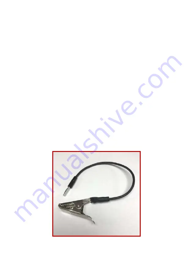
Impact Welding – Using Impact clip


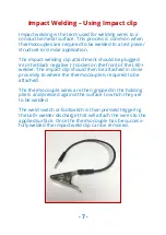
Impact welding is the term used for welding wires to a 

conductive metal surface. This process is common when 

thermocouples are required to be welded to a test piece/

structure or similar application.


The impact welding clip attachment should be plugged 

into the black negative (

-

) socket on the front of the L60+ 

welder. The impact clip should then be attached in close 

proximity to where the thermocouple is required to be 

attached.


The thermocouple wires are then gripped in the holding 

pliers and pressed against the surface to which they are 

to be welded.


The weld switch or footswitch is then pressed triggering 

the L60+ welder discharge that will attach the wires to the 

applied surface. Once the thermocouple has be success-

fully welded the impact weld clip can be removed.


-

 7 

Summary of Contents for L60+

Page 1: ......

Page 2: ...Rear Panel Controls 5 Setting Up Procedure 6 Welding Instructions 7 Impact Welding Using Impact clip 8 Pen and Plate Resistance Welding Accessory 9 Energy Settings 9 Electrodes 10 Maintenance 11 Warni...

Page 3: ...y work with minimal practice A satisfactory thermocouple junction is produced without using argon but where argon is available a momentary purge is automatically triggered immediately prior to the wel...

Page 4: ...re Holding Pliers With Lead Safety Glasses Magnifying Eyeglass Spare Carbon Electrode Spare 2A Fuse Impact clip Pen and plate Argon Hose Hexagon key for electrode change Mains Lead Footswitch Allows O...

Page 5: ...wing E Wait LED Glows when weld charge is building F Ready LED Ready to Weld indication G Power Rotary control of the capacitor charge voltage H Level selector Selects the total capacitance available...

Page 6: ...Setting Up Procedure 1 Using a suitable connector fused at 5 amps connect to mains sup ply 2 If Argon is to be utilised couple argon hose to rear of welder Do not over tighten as a good seal will be m...

Page 7: ...he switch and remove the work for examination Preparation of Wires for Arc welding For small diameter wires strip off about 12mm of insulation and twist together Then with side cutters or scissors cut...

Page 8: ...ative socket on the front of the L60 welder The impact clip should then be attached in close proximity to where the thermocouple is required to be attached The thermocouple wires are then gripped in t...

Page 9: ...is applied with moder ate pressure The weld is then triggered by the switch on the L60 or footswitch if used Test welds will determine opti mum settings for material size and composition We recom mend...

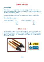
Page 10: ...l bead A flattened bead indicates that the energy setting is too high Wire Diameter mm Switch at LOW 0 1 Switch at HIGH 0 3 0 15 0 5 0 2 0 7 0 25 0 8 Electrodes To replace or adjust carbon electrode f...

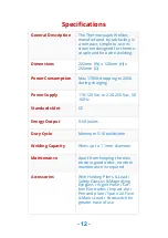
Page 11: ...elds min Weld Voltage 49 V Mechanical Physical Dimensions 220mm Wide x 120mm High x 250mm Depth Weight 4kg Electrical Power Supply 110 120 Vac or 220 250 Vac 50 60Hz Power Consumption Max 170VA droppi...

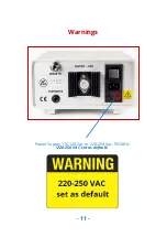
Page 12: ...Power Supply 110 120 Vac or 220 250 Vac 50 60Hz 220 250 VAC set as default 11 Warnings...

Page 13: ...r Supply 110 120 Vac or 220 250 Vac 50 60Hz Standards Met CE Energy Output 0 60 Joules Duty Cycle Minimum 5 10 welds min Welding Capacity Wires up to 1 1mm diameter Maintenance Apart from keeping the...

Reviews: