6
EDID Control
Under normal circumstances, a source device (digital and analog) will require information about a connected
device/display to assess what resolutions and features are available. The source can then adjust its output to send
only resolutions and features that are compatible with the attached device/display. This information is called EDID
(Extended Display Information Data) and a source device can only accept and read one EDID from a connected
device/display. Likewise, the source can only output one resolution for use by a connected device/display.
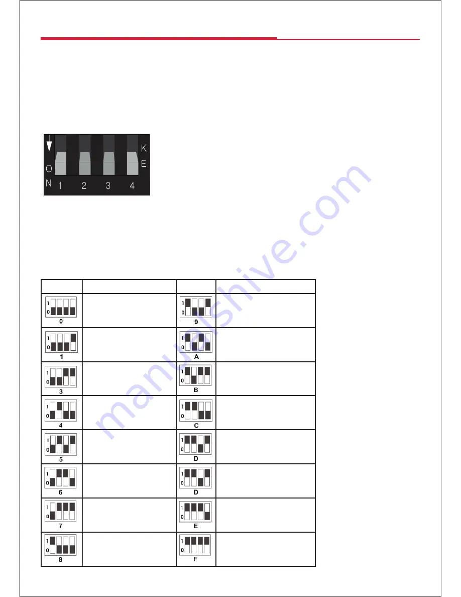
The EDID switch allows for EDID learning or to pre-set an EDID to encourage a “handshake” between the display
and source.
Manual EDID Learning Mode
When you set the switch to any of the “0-8” sttings below, the Transmitter will
set a fixed EDID for the source. See below the details for each EDID setting
description, please refer to the EDID table.
Auto EDID Learning Mode
When you switch to setting “9”, the Transmitter will copy the HDMI LOOP OUT port display EDID to source.
Attention: Please confirm the extender is working normally, if you want modify the new EDID to source, toggle the
EDID switch to the corresponding number first, then plug the Transmitter power again. The extender will send the
new EDID to the source.
Auto EDID Switch Settings on the Extender Splitter
Position
EDID Description
Position
EDID Description
1080p, 2CH AUDIO
3D,1080p, HD AUDIO
1080p, DOLBY/DTS 5.1
Copy EDID from the
Transmitter HDMI loop out
1080p, HD AUDIO
1080p, 2CH AUDIO
1080i, 2CH AUDIO
1080p, 2CH AUDIO
1080i, DOLBY/DTS 5.1
1080p, 2CH AUDIO
1080i, HD AUDIO
1080p, 2CH AUDIO
3D,1080p, 2CH AUDIO
1080p, 2CH AUDIO
3D, 1080p,DOLBY/DTS 5.1
1080p, 2CH AUDIO


