Analyser AutoSPY
®
2
As in single-ended mode, the ground terminal (GND) should be connected with the ground of the
circuit to be tested. The voltage of each AI with respect to ground must not exceed the values stated in
the table, in order to achieve correct measurement results. The maximum differential voltage (with a
gain of G = 1 this is 20 V for instance) occurs, when one input carries the maximum (+10 V with
G = 1) and the other input carries the minimum voltage (-10 V with G = 1).
Note:
Both measurement modes can be combined. Regardless of the configured measurement
mode or gain, voltages beyond ± 40 V must not be attached to any of the LabJack’s
analog inputs, in order to avoid physical damage to the device. However, this is solely a
rule to prevent damage. Voltages that exceed the limits stated in the table will be capped
to the minimal or maximal limit, respectively.
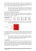
Digital inputs IO0 through IO3 and D0 through D15
The LabJack provides 20 digital inputs in total (LOW < 0.8 V; HIGH > 4 V). Four of these, referred to
as IO0 through IO3, can be connected at the right terminal block. The remaining ones, referred to as
D0 through D15, can be accessed via the DB25 connector at the narrow side of the LabJack or the
CB25 extension module that can be attached there.
Pinout of the DB25 extension
D-sub connector:
Important:
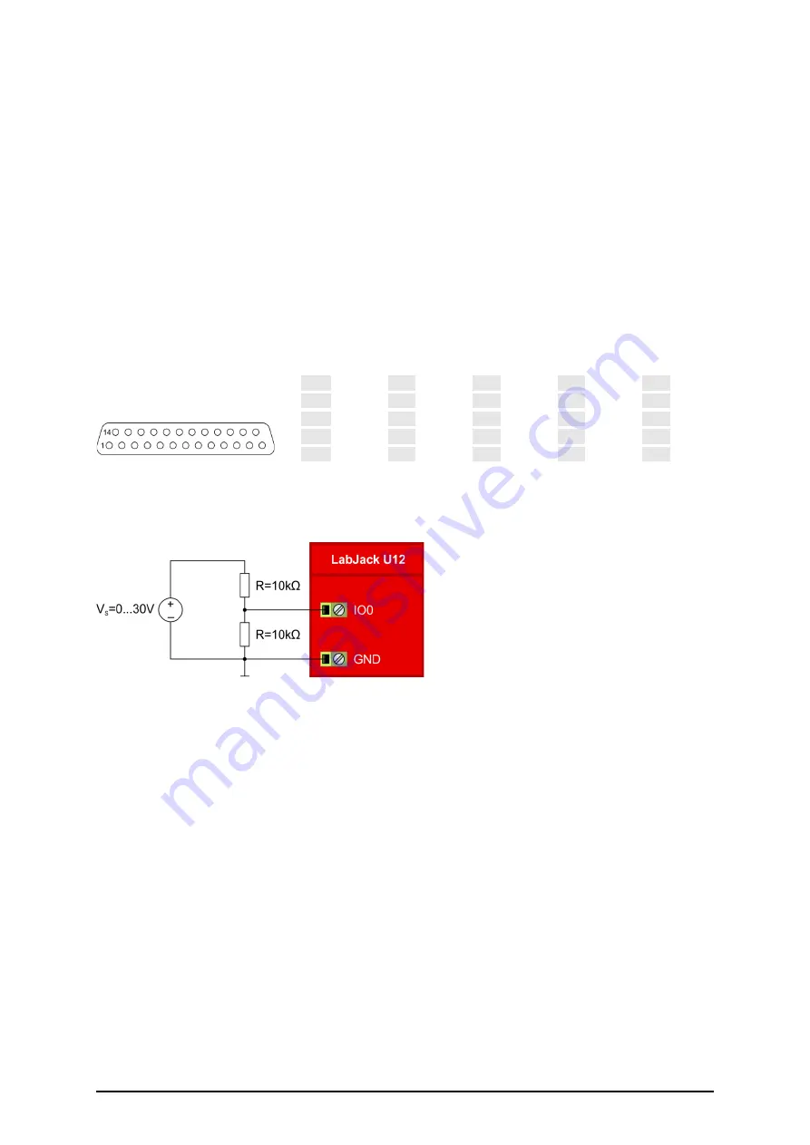
The four inputs IO0 through IO3 can be fed with voltages up to 15 V. Signals exceeding
this range (e. g. typical PLC signals)
necessarily
require an adequate protective circuit,
like the following voltage divider:
The 16 inputs D0 through D15, as they are accessible through the extension connector, are designed
for TTL signals only, and do not provide any overvoltage or short-circuit protection. The CB25 exten-
sion module, however, provides additional protection, such that voltages between -20 V and +25 V
can be connected. In this case you
must not
install the jumpers that bypass the protection resistors on
the CB25 board!
Note:
The three inputs D13 through D15 are Schmitt trigger inputs. They transit from LOW to
HIGH on an input voltage of about 2.7 V and transit back from HIGH to LOW on an
input voltage of 1.5 V. If one of these input lines carries a voltage above 9.5 V, all three
inputs transit to HIGH, caused by the LabJack’s internal wiring.
Counter Input CNT
The LabJack provides a 32 bit counter that can be connected at screw terminal CNT. The counter is
incremented when it detects a falling edge (from >4 V to <1 V) followed by a rising edge. Thus, re-
setting the counter while the attached signal is LOW will cause the first rising edge not to be counted.
The connected voltage must not 15 V in order to avoid damage to the LabJack. If necessary,
use the voltage divider circuit suggested above to protect the input. The counter can be configured to
operate in continuous mode to count piece numbers and the like, or it can be configured to reset after
each measurement to count revolutions, for instance.
1
D0
6
D5
11
+5V
16
GND
21
D11
2
D1
7
D6
12
+5V
17
GND
22
D12
3
D2
8
D7
13
+5V
18
D8
23
D13
4
D3
9
(NC)
14
GND
19
D9
24
D14
5
D4
10
+5V
15
GND
20
D10
25
D15

