background image

- 11 -

5. 

Hints

5.1. 

Repairs & Replacements

A)

Change of Tube 

Always make sure that the reason for malfunctioning is due to element failure before 
disassembling the furnace 

o

Ceramic tube can be freely changed for tube furnaces over 1400 C where 
SiC and MoSi2 heating elements are used.

Please  use  following  procedure  when  changing  tubes  for  furnaces  with  Silicon 
Carbide heating elements:
1.

Always disengage power before starting the replacement.

2.

Remove the thermocouple

3.

Remove the tube when cold (Temp. <45°C), slowly without any contact with 
the SiC heating elements.

4.

Replace the new tube.

5.

Reconnect the thermocouple.

6.

Heat the furnace till 900°C. 

Always  use  the  installment  diagram  supplied  to  change  the  SiC  and 
MoSi2 heating elements

During  reassembly  process  one  must  be  careful  to  use  the  correct  terminals. 

Reheat the Furnace to 900°C.

Do not use insulation that appears loose .Most of the time the very same insulation 

can  be  obtained  from  local  market.  We  can  of  course  deliver  the  concerned 
insulation whenever requested.

B)

Replacement of Solid State Relay

Always disengage power before opening the back panel. Use proper screw driver 

and remove the back panel or control box. Disconnect the relays, taking note of 
connection diagram and coloring of wires. Remove the dis-functioning relay using a 
screw driver and place the new one to the related rail. Close the back panel and heat 
up the furnace till 900°C. 

C)

Replacement of Thermocouple

Always disengage power before opening the back panel. Use proper screw driver. 

When  there  is  thermocouple  break  down,  the  controller  always  gives  a  related 
warning at display. When there is a problem with it remove the metal support of 
thermocouple  and  remove  the  cables  noting  the  coloring  of  connecting  cable. 
Remove the thermocouple slowly taking note not to break the ceramic sheath if 
there is any. Reverse the process and heat up the furnace.   

i

i

Summary of Contents for LSCF-100A

Page 1: ...Instruction Manual Model LHTF 100 Series Labnics Equipment High Temperature Tube Furnace Please read this manual carefully before using the instrument...

Page 2: ...Technical Properties 4 2 1 Temperature Controllers 4 2 2 Heating Elements 7 2 3 Refractory Insulation 8 2 4 Electrical Layout 8 3 What is PID Control 9 4 Points to Take Care While Operating the Furnac...

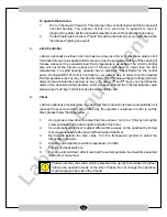
Page 3: ...serts slowly It is extremely important to remove the packing inserts from inside the furnace Operating the furnace without removal of safety inserts will cause heavy damage on the heating elements Use...

Page 4: ...b requires a qualified technician The technician who is responsible of commissioning the furnace is also responsible to act in accordance the rules of safety of European Community Technician is solely...

Page 5: ...d against risks to avoid any burns etc 6 Labnics furnaces are manufactured in conformity with CE Electromagnetic Emissions Directive Even though so electromagnetic emissions can effect some sensitive...

Page 6: ...tured at will and without informing 2 Furnace Components Related Technical Properties 2 1 Temperature Controllers Model Sensitivity PID Step definition Number of Number of Programs Segments DC 1010 1...

Page 7: ...active functions of the controller Insignia Description Active Color OUT1 OUT2 Output Relays power are active Green AT AutoTune is underway Orange AL1 AL2 AL3 Alarm signal underway Red MAN Controller...

Page 8: ...play any programming profile has to have the cooling stage defined as well Use a paper to draw your program profile before data feed in We advice the PVSTART option to be enabled to ease the running o...

Page 9: ...y Used to either to decrease a value or to inactivate a function 2 2 Heating Elements Labnics employs Kanthal originated heating elements in furnaces 2 2 1 Wire elements The basic advantages of Kantha...

Page 10: ...s of service as a heating element The resistance of Kanthal Super elements does not change due to ageing even after having been in operation for a long time at high temperatures Due to these propertie...

Page 11: ...erature and it should never be used over this temperature The heating elements and the concerned insulation are related with designated o maximum temperature of furnace It is most advicable to us a fu...

Page 12: ...a new one The old unbroken element should be kept aside to be used in pairs with an old element At high temperatures a glassy phase coating appears on SiC elements This coating although not harmful to...

Page 13: ...use insulation that appears loose Most of the time the very same insulation can be obtained from local market We can of course deliver the concerned insulation whenever requested B Replacement of Sol...

Page 14: ...ently asked questions FaultAnalysis 1 Furnace controller does not display when the I 0 switch turned on 1 1 Check the Mains supply Check the voltage present May be less than 220V 1 2 Check the fuses o...

Page 15: ...1 Electrical Other Requirements Phase Volts Frequency Medium Temp Humidity Single 220V 50Hz 5 C 40 C Max 85 Triphase 380 220V 50Hz 2 Control Panel Honeywell DC1010 UDC2500 Honeywell DC1010 Honeywell U...

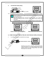
Page 16: ...igits can be activated by pressing key By using and keys you can define the digits of the desired limit temperature After you have entered the limit temperature value please press set key in order to...

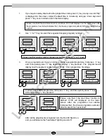
Page 17: ...ys in the manual mode and open red the I 0 switch Furnace will start heating directly to set temperature 2 Programme Mode See Section C page 11 and Section D page 15 for further details Press key cont...

Page 18: ...well time has expired 2 Use or key to select the requested recepie program number Please note that program number changes as the operator press or keys 3 Once a programme is chosen in order to run the...

Page 19: ...rogramme data during operation E Sample Program Honeywell UDC2500 There are four different alternatives in order to heat up the furnace with UDC2500Temperature Controller 1 Standard Heating 2 To defin...

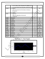
Page 20: ...o next step ENDSEG End Segment max 12 The segment number which the programe will end RPUNIT Engineering Unit for Ramp TIME Defines heating up or cooling down speed Can be chosen as TIME Hr Min EU H C...

Page 21: ...t point Unit is Hr Min SG3RP RampTime 3 1hr SG4SP Soak SP 4 400 SG4TI SoakTime 4 1hr SG5RP RampTime 5 1hr 30min SG6SP Soak SP 6 250 SG6TI SoakTime 6 3hr 0min SG7RP RampTime 7 2hr 30min SG8SP Soak SP 8...

Page 22: ...rts Replaced Parts Recommended Action Required Yes Service Engineer s Name Signature Requisition Number Customer s Name Signature Date Stamp Page ____ Of ____ No Model Serial No Date Status OK Install...

Page 23: ...Labnics Equipment 43040 Christy St Fremont CA 94538 USA Toll Free 877 620 9992 Tel 925 271 4322 Fax 925 886 0400 Email info labnics com Website www labnics com...

Reviews: