background image

BA_078_en_10.01 Level transmitter PASCAL Ci4 LEVEL 

Page 18/36 


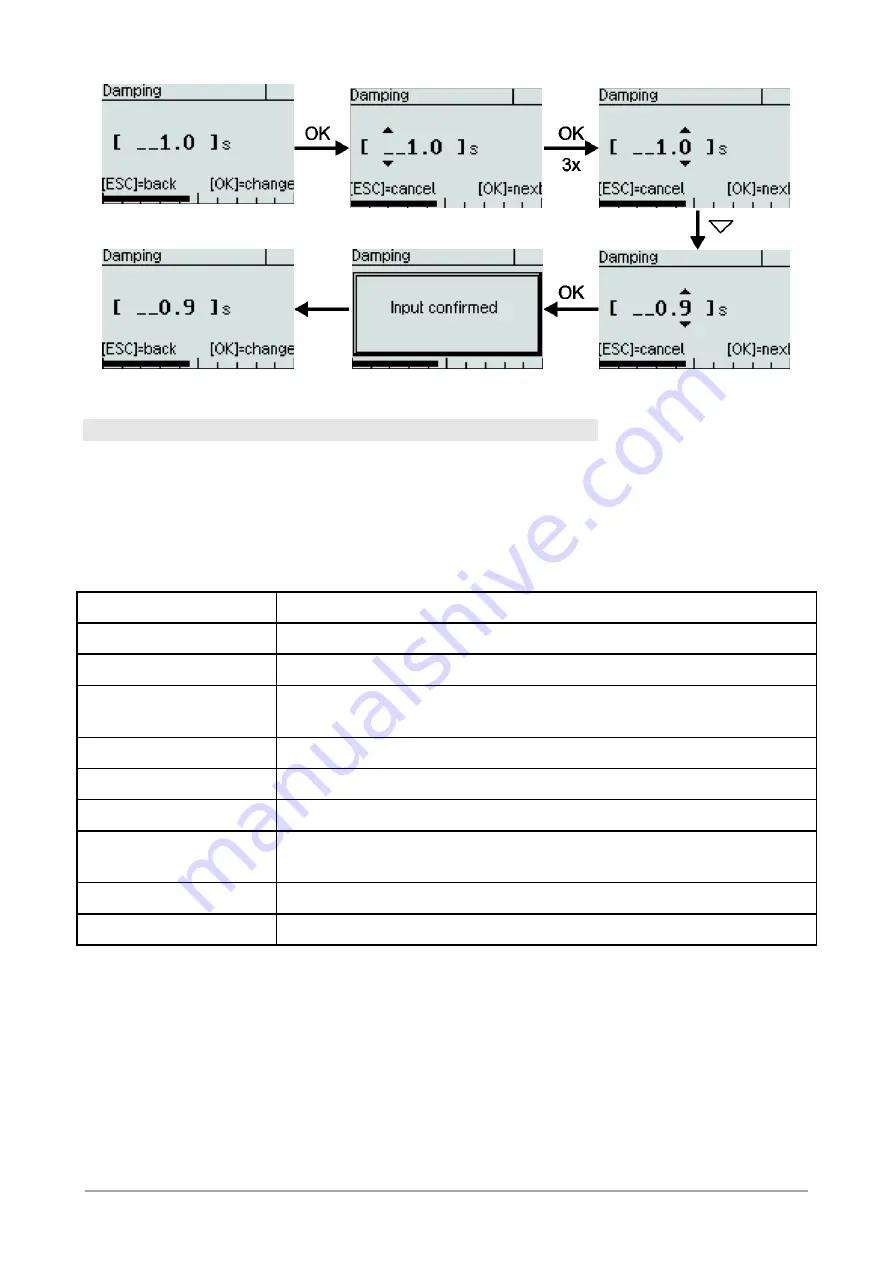
Figure 17: Procedure for setting a numeric value (e.g. from 1.0 to 0.9) 


  6.5    The Menue Tree 


In the following,  the display and adjustment options are described by their position in the 
menue  tree.  An  overview  of  the  menue  tree  can  be  found  on  the  last  page  of  this  docu- 
ment. 


6.5.1 

Main menue 

The main menue has the following entries: 


Menue entry 

Description 

Quick setup 

Selection of the most important settings 

Level 

Parameterisation of level measurement 

Adjustment 

Adjustment functions for pressure measurement and current out- 
put 

Display 

Functions for configuring the display 

Measurement/output 

Configuration of the measuring rate, damping and current output 

Diagnosis 

Diagnostic information such as min/max values 

Simulation 

Simulation of current or one of the possible measurands for func- 
tion check of the measurement chain 

Communication 

Information and settings regarding HART communication 

System 

Device data and function such as factory reset 

Table 6: The main menue 

Summary of Contents for PASCAL Ci4 LEVEL

Page 1: ... devices 3 3 3 Mechanical Installation 3 3 4 Electrical Connection 3 3 5 Devices with Diaphragm Seal 4 3 6 Mounting the Remote Display 4 4 Operation 5 4 1 Test Terminals 5 4 2 Remove Display Activate Write Protection 6 4 3 Maintenance Service 6 5 Disassembly 7 6 User Manual 8 6 1 Principles of the parameterisation concept 8 6 2 Basics of the Operating Concept 11 6 3 Display Mode Measured Value Dis...

Page 2: ...rocess and undamaged The device is intended to measure pressure of gases vapors and liquids as specified in the data sheet The CE marking on the device certifies its compliance with the applicable EU Directives for placing products on the market within the European Union You find the complete EU Declaration of Conformity document no KE_042 at www labom com If you purchased a device with EX approva...

Page 3: ...ower process connection and the minus side to the upper process connection 3 3 Mechanical Installation Use gaskets if required that are suitable for the process connection and resistant to the media Before starting operation check the process connection carefully for leaks under pressure You can use the device in any mounting position Normally the transmitter is adjusted for a vertical mounting po...

Page 4: ...pipe mounting for pipe diameters from 30 64 mm For pipe mounting you can order the corresponding U bolts from LABOM For best EMC protection only use the included cable If you ordered the remote display together with the device the assembly has been com pleted in the factory You only need to route the cable and mount the housing with the re mote display If you have received the remote display as a ...

Page 5: ...ay and control unit after installation During operation take care that the device remains within its intended pressure and tem perature ranges No other monitoring is necessary Permissible ambient temperature 40 80 C 4 1 Test Terminals You can check the output current without interrupting the current loop using the test ter minals on the terminal board When you connect a current meter to the Test a...

Page 6: ...refully Figure 5 Removing the display After removing the display module you can reach the DIP switch on the CPU module The write protection is active when the DIP switch is in the ON position Figure 6 Write protection via slide switch in the device Re mount the display module in the reverse order 4 3 Maintenance Service When properly installed in accordance with applicable specifications this devi...

Page 7: ...ng pressurized lines might cause severe injuries Danger of severe injuries or damage Relieve the process pressure before attempting to remove the device Shut off the pressure supply for all feed lines to the device and relieve the pressure in them Warning Hazardous deposits and residues might remain on opened process connec tions and removed devices Danger of injury After the device has been remov...

Page 8: ...ze and shape of the tank must be defined for calculating the volume and weight NOTE It would be physically correct to refer to the fill amount as a mass However the not quite correct term weight is recognised in everyday language The aim of the parameteri sation concept is to realise an intuitive access The term fill weight and not fill mass is therefore used below 6 1 1 The reference point for le...

Page 9: ...not affect the tank shape definition The table is managed internally in metre litre pairs and converted for the display depend ing on the units selected The display therefore adapts accordingly to the table when con verting the height and volume unit 6 1 3 Scaling the current output Each of the level variables height volume weight as well as the measured pressure for calibration purposes can be is...

Page 10: ...ght from the fill vol ume 6 1 5 Summary of the parameterisation concept 1 The fill height is calculated from the measured pressure using the density and height offset 2 The fill volume is calculated from the height using the tank shape table 3 The fill weight is calculated from the volume using the density 4 A manual selection determines which of these measurands should be issued at the current ou...

Page 11: ...s and hold the ESC button you always return to the measured value display Button Function Select function increase decrease value OK Confirm selected function or selected value ESC Cancel action ESC long Return to measured value display Table 1 General button functions The structure of the display is the same in every operating mode The display area is di vided into four zones Header Icon indicati...

Page 12: ... an inappropriate unit the largest displayable number is shown flashing In this case please select a different setting of the decimal point or a different unit In display mode you can review the device data enter the menue or lock unlock the menue Button Function Scroll through the pages with device data ESC Return to measured value display OK Go to the operating menue ESC OK long Activate deactiv...

Page 13: ... icon Use the same key combination to unlock the menue again The menue cannot be un locked with the key combination if the hardware DIP switch is activated 6 3 3 Icons indicating device status In the top right corner of the display depending on the device status an NE107 conform icon is displayed The following icons are defined Error failure Critical error alarm current is activated The error desc...

Page 14: ...n use the entire display width Horizontal bargraph Three val ues Under the main value two additional values are shown Both of them can use the entire display width Horizontal bargraph Two values Two values are shown in the same size one below the other Horizontal bargraph Large dis play The main value is shown at the maxi mum size best readability from a dis tance One additional value can also be ...

Page 15: ...navigate in the menues by using the arrow buttons The selected menue item is indicated by triangles on the left and right The OK button selects the menue item or switches to the corresponding submenue You can return to the higher level menue by pressing ESC From the main menue pressing ESC returns to the meas ured value display From every position in the operating menue you can return to the measu...

Page 16: ...ess OK to switch to edit mode to change the parameter After this is done the display will then switch back to view mode so that you can check the new setting 6 4 1 1 Selection of a value from a selection list Up to three options are shown at the same time in one selection list When the selection list is longer a scroll bar on the left side of the display indicates the position of the selected item...

Page 17: ...iangle above and below the number By pressing OK you go to the next digit Figure 16 Elements when setting a numeric value You change the selected digit by pressing the or button The higher value digit is also increased or decreased when passing zero For instance you can easily go from 19 to 20 without having to edit two digits Lower value digits are not influenced unless the parameter limit is rea...

Page 18: ...uick setup Selection of the most important settings Level Parameterisation of level measurement Adjustment Adjustment functions for pressure measurement and current out put Display Functions for configuring the display Measurement output Configuration of the measuring rate damping and current output Diagnosis Diagnostic information such as min max values Simulation Simulation of current or one of ...

Page 19: ...amping Setting the damping of the output signal see 6 5 6 1 Device ID Setting the device ID see 6 5 10 1 Config memory Configuration memory reading writing and status see 6 5 10 3 Table 7 Quick Setup menue 6 5 3 Level menue All settings to parameterise the level measurement can be found in the Level menue Menue item Description Level wizard Guided parameterisation of the fill level measurement Den...

Page 20: ...er PASCAL Ci4 LEVEL Page 20 36 6 5 3 1 Level wizard The fill level wizard allows the easy parameterisation of the device You are guided through all the necessary setting dialogue boxes Figure 18 Guided dialogue boxes in level wizard ...

Page 21: ...is that the height offset is correctly set and the fill height relative to the level ze ro can be determined with sufficient accuracy The device calculates the density from the measured pressure and the entered fill height and suggests the density to be saved Figure 19 Teaching in the density 6 5 3 3 Height offset submenue You can view change or teach in the height offset in this submenue You can ...

Page 22: ... 11 Density submenue Enter or teach in the tank shape A basic requirement for the correct recording of the tank shape is the correct parameteri sation of the density and height offset Entering and teaching in the tank shape can be combined as required For example you can teach in the torispherical head of a tank and enter the cylindrical part of the tank by adding control points manually It is man...

Page 23: ...h in process two control points will be very close together which can lead to problems with the volume calculation The odd control point is deleted after checking for closely located control points Checking the volume values avoids input errors The table cannot be switched on if the volume values are not also sorted in rising order after sorting the height values The level zero applies to all fill...

Page 24: ...he static pressure measurement For these devices there is an additional menue entry called Zero point pst 6 5 4 1 Zero point correction The zero point correction requires a non pressurized pressure port e g during calibration in the lab When executing this function the applied pressure will be interpreted as zero bar relative pressure The zero point correction results in an offset of the whole cha...

Page 25: ...ce at 900 mbar rel The reference pressure level for the upper offset can also be freely chosen To ensure that the adjustment is as precise as possible the upper and lower adjustment should be performed as close as possible to the lower range value and upper range value of the measurement ranges 6 5 4 4 Current adjustment You can use the current adjustment if the reading at the end of the measureme...

Page 26: ...of decimal places Backlight Switch backlight on off Table 14 Display menue 6 5 5 1 Submenue Units You can select the unit of every value shown on the display These settings do not affect the internal calculations of the device or HART communication The shown conversions are only meant for your orientation The device uses conversion values with ten decimal places Fill height unit The unit in which ...

Page 27: ...eight unit The unit in which the measured weight should be displayed can be selected from the fol lowing list Unit Description g Gramme 1 g 0 001 kg kg Kilogramme 1 kg 1000 g 0 001 t t Tonne 1 t 1000 kg lb Pound 1 lb 0 4536 kg Table 17 Possible weight units Density unit The unit in which the density should be entered and displayed can be selected from the following list Unit Description g cm3 Gram...

Page 28: ...si Pound force per square inch 1 psi 68 9 mbar atm Atmospheric pressure 1 atm 1013 mbar mmH2O Millimetre water column 1 mmH2O 0 0981 mbar mH2O Metre water column 1 mH2O 98 1 mbar inH2O Inch water column 1 inH2O 2 49 mbar ftH2O Foot water column 1 ftH2O 29 84 mbar Torr Torr 1 Torr 1 mmHg 1 33 mbar mmHg Millimetre mercury column 1 mmHg 1 33 mbar inHg Inch mercury column 1 inHg 33 86 mbar Table 19 Po...

Page 29: ... In addition you select and parameterise the measurand to be shown at the current output Menue entry Description Damping Setting the damping of the output signal Measuring rate Setting the measuring rate 20 or 100 Hz Select output value Select value that shall be shown at the current output height volumen weight or pressure Value at 4 mA Value of the selected measurand that should correspond to 4 ...

Page 30: ...red and the current is calculated and imprinted in the current loop When a particularly fast measuring rate is required for instance to detect pressure peaks you can increase the measuring rate to 100 Hz This can lead to the following restrictions Communication via HART can be disturbed by fast pressure changes The measuring signal can be noisier For this reason you should only increase the measur...

Page 31: ...easured value display in the device data see 6 3 1 Figure 25 Display and resetting of the Min Max values for pressure 6 5 7 2 The maintenance timer Using the maintenance timer the device can signal the need for maintenance after a freely selectable number of operating hours The timer counts down from the start value Mainte nance need is indicated by an icon in the display see 6 3 3 and if necessar...

Page 32: ...ation menue 6 5 9 1 HART address This address corresponds with the short address which is used for the HART Communication It can be set within a range of 0 to 63 Please note that setting the short address between 1 and 63 will not automatically activate the constant current mode This must be done under the menue Current mode see 6 5 9 2 6 5 9 2 Current mode The current mode determines whether the ...

Page 33: ... display module You can transfer the data back to the device or to another device Transferring a configu ration to another device requires a compatible target device The same nominal range is not necessary It is sufficient if the measuring range of the stored configuration is equal or smaller than the nominal range of the target device The configuration memory contains the parameter setting of the...

Page 34: ...BA_078_en_10 01 Level transmitter PASCAL Ci4 LEVEL Page 34 36 ...

Page 35: ...BA_078_en_10 01 Level transmitter PASCAL Ci4 LEVEL Page 35 36 6 5 11 Overview with menue tree and device functions ...

Reviews: