background image

4 Initial Setup

CZM6


Stereo Zoom Microscope User Manual

5

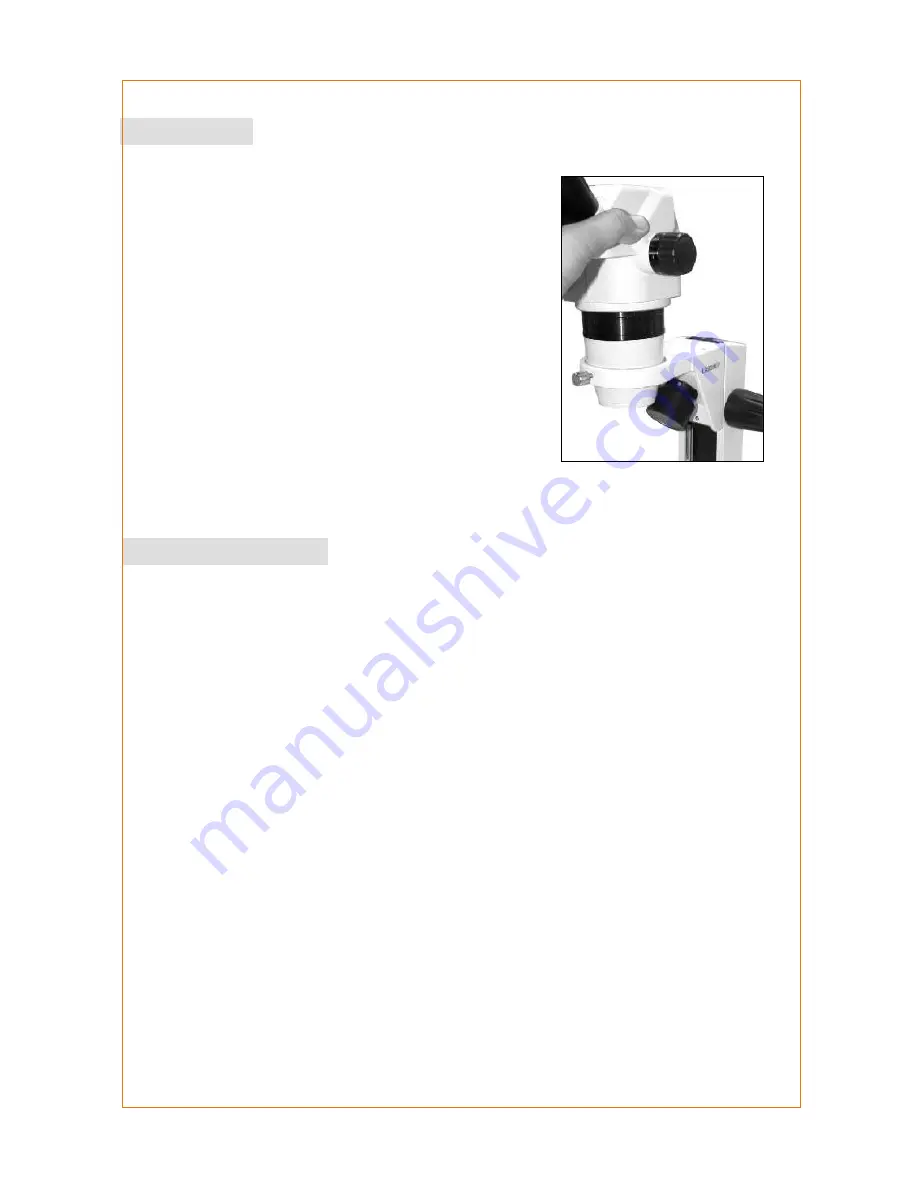
Observation Head

Remove observation head from Styrofoam box and follow the 
following steps:

(i)

Loosen  the  Head  Locking  screw  provided  in 
microscope pod.

(ii)

Place  the  Observation  Head  on  the  pod  and 
secure by tightening the Head Locking screw.

Eyepieces  -  Insert  both  eyepieces  into  the  ocular  tubes 
provided in the Observation Head and confirm the fitting is 
secure.

Install  Glass  Stage  or  Black  and  White  Plate  on  the  base 
cavity and hold plate down with stage clips provided.

This procedure explains how to use CZM 6 Microscope, it does not include information on general 

techniques of stereo zoom microscopy.

!

Place the specimen to be observed in the center of the glass plate (or Black & White Plate)

!

Verify that all exposed optical surfaces are free of any particulate debris. Plug the male end of 

the provided power cord into a grounded outlet and the female end into the microscope base. 

Turn ON the main power supply by toggling the ON/OFF switch provided at the back of 

microscope base. Switch on the incident and/or base lamps as required toggling the corre-

sponding ON/OFF switches provided on the front panel of the microscope base.

!

Rotate the zoom control knob until the low magnification is achieved.

!

Adjust the interpupillary distance by adjusting the two ocular tubes inwards/outwards until both 

eyes are able to fixate on one common circular field while looking through the eyepiece.

!

While looking through the eyepieces, adjust the microscope focus position 

!

along the vertical 

axis by adjusting the focus knob(s) provided on either side of the stands arm.

When a feature / region of interest needs augmentation, rotate the zoom control knob to adjust 

the magnification.

5 Operating Procedure

Summary of Contents for CZM6

Page 1: ...ideas for vision CZM6 Stereo Zoom Microscope User Manual To ensure proper use of this instrument as well as to avoid injury while operating instrument understanding this manual completely before use i...

Page 2: ...nitial Set up 5 5 Operating Procedure 5 6 Fine Adjustment of Binocular Head 6 7 Changing Magnification 6 8 Changing Bulb for Incident Transmitted light 7 9 Changing bulb for Transmitted Illumination 7...

Page 3: ...each tailored for disparate applications A keen attention to user convenience has been incorporated in both the mechanical and optical systems of this precision instrument Superior levels of clarity...

Page 4: ...Viewing Body Stage Plate On Off switches for incident and transmitted illumination Focusable Eyepiece Zoom Control Knob Focussing Knob Stage Clips Incident Light 2 Photographic View CZM6 Stereo Zoom...

Page 5: ...Trinocular Viewing Body Stage Plate On Off switches for incident and transmitted illumination Focusable Eyepiece Zoom Control Knob Focussing Knob Stage Clips Incident Light CZM6 Stereo Zoom Microscop...

Page 6: ...nocular Zoom Pod 1 6 9 Trinocular Zoom Pod 1 6 9 Optional EYEPIECES 10x WF FN20 Fixed type 10x WF FN20 Focusable type 10x WF FN22 Fixed type 10x WF FN22 Focusable type Standard 16x WF FN16 Fixed type...

Page 7: ...ed optical surfaces are free of any particulate debris Plug the male end of the provided power cord into a grounded outlet and the female end into the microscope base Turn ON the main power supply by...

Page 8: ...es to compensate for any refractive error in the eye Set diopter on both eyepieces oculars to zero Focus the specimen with focusing knobs After best possible focus is achieved adjust the circular diop...

Page 9: ...ing by anti clockwise rotation 4 Using tissue paper replace the old bulb and insert new bulb in bulb cavity CAUTION To avoid any injury please make sure microscope has been off for at least 15 minutes...

Page 10: ...fuse Remove power plug from microscope before doing any replacement of fuse Use a flat Head Screwdriver to rotate and remove the fuse holder from theAC inlet socket The walled fuse is the live fuse a...

Page 11: ...T emp 5 C 40 l Relative Humidity Maximum 80 at temp upto 31 C l Supply voltage shall not exceed10 of the rated input voltage Caution High Voltage Fuse Replacement Warning High Voltage Power Inlet Ear...

Page 12: ...042 Dual Light Stand 4122086 000 SB Stand w o Top light 412088 000 Size L 245 xW 175 x H 320mm Size L 245 xW 175 x H 260mm Size L 245 xW 250 x H 385mm Size L 245 xW 175 x H 270mm Size L 245 xW 175 x H...

Page 13: ......

Reviews: