background image

Fig. 5

Fig. 6

1

2

3

4

Fig. 8

A

B

Fig. 7

1

2

R

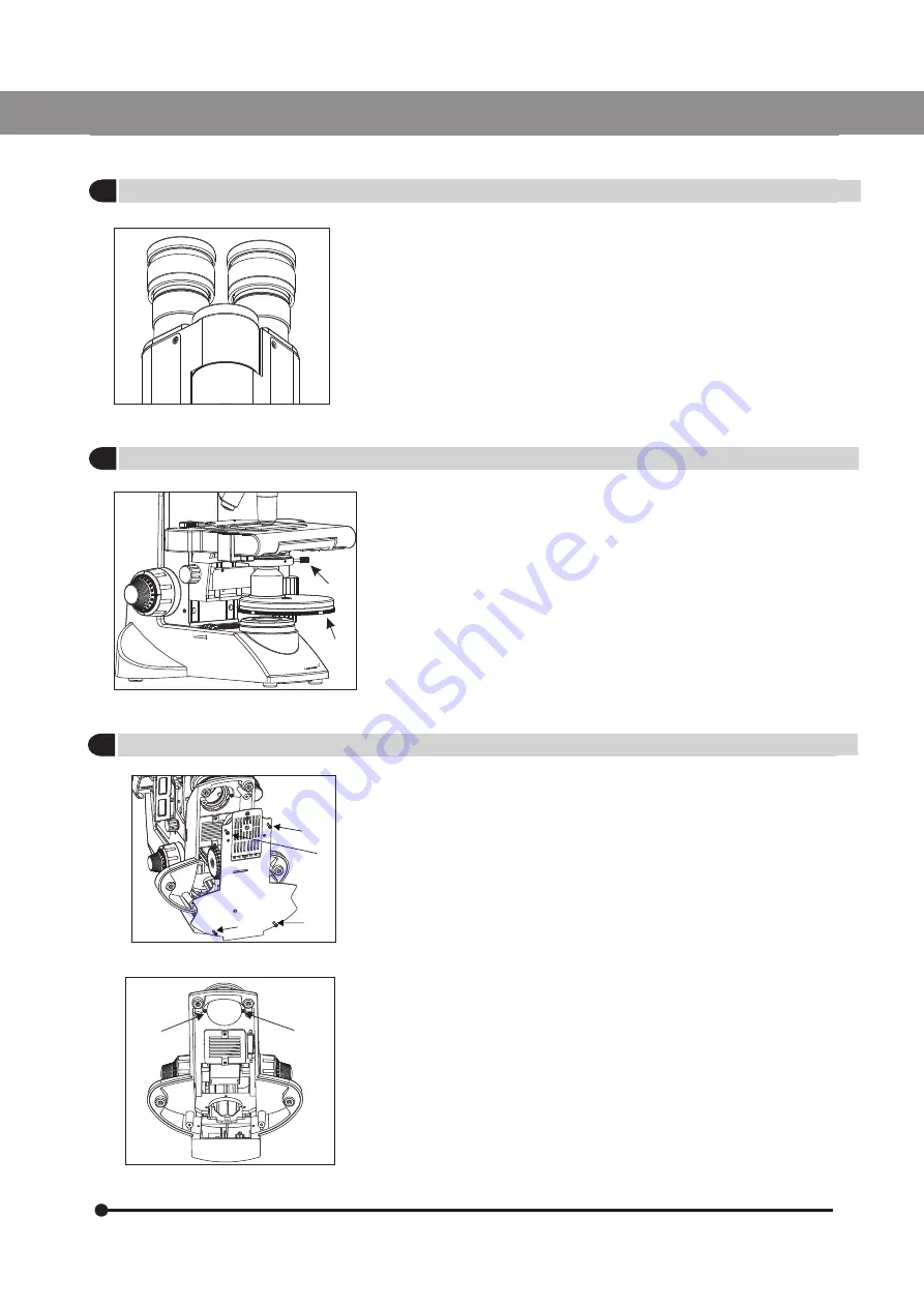
10X eyepieces are provided. To replace:
1. Pull out the 10x eyepieces out from the observation heads
     Ocular tube. 
2. Insert desired eyepieces in empty ocular tube.

1. Remove the condenser from its position by loosening the thumb
   screw (1) on right side of the condenser bracket as shown in
     figure  6. 
2. Place the phase annulus turret in position from where the
     condenser has been removed. 
3. Secure it with thumb screw (1). The phase turret can be adjusted
    at any desired phase annulus (10x, 20x, 40x & 100x) by turning
     the  thumb wheel (2) to the desired position. There is also an ‘0’
     setting on the thumb wheel for bright field application.  

Note: Refer to the user manual provided with the Phase Contrast
fit for centering and alignment. 

Procedure for Koehler Installation Kit (figure 7-11)
1. Lay the microscope on a clean surface toward right so that the
     microscope base is exposed. 
2. Using a screw driver, unscrew four screws (1 to 4) from (figure 7)
     to open the base of the microscope. 
3. Remove two screws (A) ans (B) from (figure 8) to open the
     illumination mount and replace it with Koehler mount.  

10

Lx 400

OPTIONAL EYEPIECES

PHASE TURRET 

INSTALLING THE KOEHLER ILLUMINATION KIT

2

3

4

9126000-795 

 Lx 400 

Issue 1.5

Printed on April,2019

Summary of Contents for Lx 400

Page 1: ...1 5 Printed on April 2019 Lx 400 Research Microscopy User Manual To ensure proper use of this instrument as well as to avoid injury while operating Instrument understanding this manual completely befo...

Page 2: ......

Page 3: ...OUR MICROSCOPE 7 6 STANDARD COMPONENTS 8 7 OPTIONAL ACCESSORIES 9 11 8 INITIAL SETUP 12 9 ASSEMBLY 13 14 10 SUMMARY OF BRIGHT FIELD OBSERVATION PROCEDURE 15 11 DETAILED OBSERVATION PROCEDURE 16 20 12...

Page 4: ...e All positions are par centered and par ensuring the highest level of accuracy The ball bearing mechanical stage allows smooth travel over a 78 x 54mm area with spring loaded stage clamps for retaini...

Page 5: ...replace your microscope bulb allow lamp socket and bulb to cool before touching Fig 1 Applicable bulb LED replacement 6V20W Halogen bulb P N CX 013 6V30W Halogen bulb P N EL 455 or LED P N 9135000 90...

Page 6: ...roleum and isopropanol are highly flammable they must be handled carefully Be sure to keep these chemicals away from open flames or potential Sources of electrical sparks For Example electrical equipm...

Page 7: ...le dirt with distilled water If this is unsuccessful repeat using a solution of diluted hand soap liquid Remove any remaining residue with a dry cotton swab 5 To remove oil use a solution of diluted h...

Page 8: ...rvation tube Clamping screw Coarse and fine focus knob Mechanical stage On Off intensity regulator Specimen holder Revolving nose piece Objectives Eyepieces Abbe condenser Filter holder R Lx 400 BINOC...

Page 9: ...ving nose piece Objectives Specimen holder Coarse and fine focus knob Mechanical stage Observation tube clamping screw Trinocular viewing tube Trinocular Port Abbe condenser Filter holder R 6 Lx 400 L...

Page 10: ...Microscope Arm Observation head Eyepieces Power Cord UNPACKING YOUR MICROSCOPE 7 Lx 400 5 9126000 795 Lx 400 Issue 1 5 Printed onApril 2019...

Page 11: ...ed at 10x R STANDARD COMPONENTS After removing your microscope from its packaging make sure that all of the following contents are present Please note that the contents of your microscope may vary as...

Page 12: ...pril 2019 ABBE CONDENSER 0 6 ABBE CONDENSER 1 25 POLARIZING KIT WF 16x WF 10x WF 20x TRINOCULAR HEAD BINOCULAR HEAD RP 4x RP 10x RP 40x SL RP 20x RP 50x SL OIL RP 100x SL OIL RP PH 10x RP PH 20x RP PH...

Page 13: ...40x 100x by turning the thumb wheel 2 to the desired position There is also an 0 setting on the thumb wheel for bright field application Note Refer to the user manual provided with the Phase Contrast...

Page 14: ...n assembly as in figure 9 by rotating the T Ring Replace the lens B with frosted lens provided with the Koehler kit Secure the lens assembly back 5 Close the base cover with screws 6 Replace the blue...

Page 15: ...provided in dovetail cavity as well as on observation head dovetail 2 Mount the Observation Head by engaging the dovetail provided at the bottom of the head into the dovetail cavity provided in the mi...

Page 16: ...LABOMED may lead to a fore hazard or and low illumination Fingerprints or stains on the lamp bulb reduce its life If contamination occurs wipe bulb surface with a cloth slightly moistened with alcoho...

Page 17: ...6 Reverse steps 5 to 1 to complete the process This filter modifies the color of observation light into a natural daylight color Fit the filter 1 into the bottom of the condenser 2 until it clicks int...

Page 18: ...is diaphragm Engage the objective to be used in the light path and bring the specimen in focus Engage the required filters if not pre installed Adjust the observation tube and eyepieces Adjust the int...

Page 19: ...3 outward by pulling on lever handle 1 place the specimen by sliding the specimen glass plate s on the stage from the front toward the slide seat at the rear 3 After positioning your specimen slides...

Page 20: ...region of interest after scanning the slide Figure 24 1 The horizontal coordinate can be read at position 1 on the specimen holder 2 The vertical coordinate can be read at the index line 2 Focusing P...

Page 21: ...can be quickly referred to in the future This is happen when multiple users work with the microscope Procedure for adjusting the diopter 1 Rotate the right eyepiece to match the center of the diopter...

Page 22: ...iaphragm 6 Now optimize base diaphragm by floating it and center it fig 29 7 Leave the base diaphragm at the final position Close the base diaphragm fully The condenser is most often used in the highe...

Page 23: ...bjective and rotate the fine adjustment knob to bring the specimen into focus Caution Since air bubbles in the oil will affect the image quality make sure that the oil is free of bubbles To remove bub...

Page 24: ...ances These may damage the optical surfaces Remove coarse dirt splashes or blood etc using distilled water to which a dash of household dish washing liquid has been added Wipe the surface only with a...

Page 25: ...essure Temperature Rel Humidity without condensation Air Pressure 500hPa 1 060hPa 700hPa 1 060hPa 10 100 30 90 40 C 70 C 10 C 40 C The unit meets the essential requirements of directive 73 23 EEC Low...

Page 26: ...Disposal must comply with locally applicable laws and regulations 23 DISPOSALS 13 Lx 400 9126000 795 Lx 400 Issue 1 5 Printed onApril 2019...

Page 27: ...sion oil is not used with an immersion objective Use immersion oil as suggested Pg 20 Bubbles are present in immersion oil Remove the bubbles by agitation Pg 20 The specified immersion oil is not used...

Page 28: ...ss between 0 9 and 1 4mm 9 Bulb LED does not turn On Bulb LED is not mounted Attach a bulb LED Bulb LED is blown Replace the bulb LED The power cord is unplugged Not firmly secured Ensure power cord i...

Page 29: ...hable N A 1 25 Aperture iris diaphragm Built in 7 Dimensions Weight 284 0mm L x 227 0mm W x 360 6mm H 7 kg net 8 Electrical Halogen 6V 20W 6V 30W Charging time Upto 2 000 hours Upto 500 hours LED Batt...

Page 30: ...27 DIMENSIONS 16 Lx 400 9126000 795 Lx 400 Issue 1 5 Printed onApril 2019...

Page 31: ...Revision History Rev No Date of Release Change App By ECR 1 5 March 27 2019 System Diagram S Bal ECR 08 19...

Page 32: ...hone 510 445 1257 Fax 510 991 9862 E mail sales laboamerica com www laboamerica com Labomed Europe Essebaan 50 NL 2908 LK Capelle a d IJssel The Netherlands Tel 31 0 10 4584222 Fax 31 0 10 4508251 E m...

Reviews: