MSD Legend Series Operation & Maintenance Manual | 9
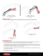
reMOVe TrANSPOrT PiN
STOW TrANSPOrT PiN
Stowed Transport Pin
Figure 12
HYDRAULIC INSTALLATION
Note: refer to “Hydraulic Schematics” on page 49.
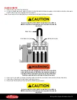
Do not connect hydraulic lines while they are pressurized.
Escaping fluid under pressure can penetrate the skin, causing
serious injury.
Hydraulic Circuit Requirements
Note: Values given are standard values. For custom attachments reference the parts manual.
Model
Jaw Cycle Circuit (Max)
Rotation Circuit (Max)
Connection
MSD1000
80 GPM (300 LPM)
4000-5500 PSI (275-380 Bar)
3-4GPM (11-19 LPM)*
2000-2500 PSI (138-172 Bar)
Cylinder: 1 inch Code 62
Rotation: -8 FFORX
MSD1500
110 GPM (410 LPM)
4000-5500 PSI (275-380 Bar)
Cylinder:1 inch Code 62
Rotation: -8 FFORX
MSD 2000
130 GPM (490 LPM)
4000-5500 PSI (275-380 Bar)
5-7 GPM (19-30 LPM*
2000-2500 PSI (138-172 Bar)
Cylinder: 1.25 inch Code 62
Rotation: -8 FFORX
MSD 2250
135 GPM (511 LPM)
4000-5500 PSI (275-380 Bar)
8-10 GPM (30-42 LPM)*
2000-2500 PSI (138-172 Bar)
Cylinder: 1.25 inch Code 62
Rotation: -8 FFORX
MSD 2500
140 GPM (530 LPM)
4000-5500 PSI (275-380 Bar)
8-11 GPM (30-45 LPM)*
2000-2500 PSI (138-172 Bar)
Cylinder: 1.25 inch Code 62
Rotation: -8 FFORX
MSD 3000
150 GPM (560 LPM)
4000-5500 PSI (275-380 Bar)
8-11 GPM (30-45 LPM)*
2000-2500 PSI (138-172 Bar)
Cylinder: 1.25 inch Code 62
Rotation: -8 FFORX
MSD 4000
180 GPM (680 LPM)
4000-5500 PSI (275-380 Bar)
Cylinder: 1.25 inch Code 62
Rotation: -8 FFORX
MSD 4500
200 GPM (750 LPM)
4000-5500 PSI (275-380 Bar)
Cylinder: 1.5 inch Code 62
Rotation: -8 FFORX
*Rotation flow specifications are an estimate. Adjust your specific flow so that the shear rotates at 3-6 RPM. Rotating
faster than 3-6 RPM can cause rotation component damage.
1.
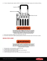
Connect the hydraulic hose to the connections located on each side of the head.
Note: each port on the head is labeled so users can easily identify the cylinder, rotation and case drain ports.
2.
For rotating models, after installing the hydraulic circuits on the base machine, install additional hydraulic lines up
the boom.
•
Two 1/2” (13 mm) diameter feed lines


