background image


ILLUSTRATED SYMBOLS 


Various symbols are used in this safety manual in order to use the unit without 

danger of injury and damage of the unit. A list of problems caused by ignoring 

the warnings and improper handling is divided as shown below. Be sure that you 

understand the warnings and cautions in this manual before operating the unit.


CAUTION


BLACK WITH YELLOW BACKGROUND 

LIGHTNING BOLT 

CAUTION, RISK OF ELECTRICAL SHOCK 


WARNING 

BLACK WITH YELLOW BACKGROUND 

EXCLAMATION POINT 

CAUTION, REFER TO ACCOMPANYING DOCUMENTS 


1.  Move the freezer to an indoor location, and plug the freezer into an appropriate 

outlet with an adequate power supply. Consult your maintenance department for 

additional information on the proper electrical configuration for this unit. 


2.  Once plugged in, the compressor(s) will start to operate and pull down to the 

setpoint on the temperature control.  


3.  Allow the freezer to reach the setpoint temperature. Depending on the size of 

the unit, this may take up to 12 hours.  


4.  Product can now be loaded into the freezer for storage. 


Unit Information


MEANING OF ILLUSTRATED SYMBOLS 


UNIT REQUIREMENTS 

STARTING INSTRUCTIONS 

Summary of Contents for MV85 Series

Page 1: ...er outlet installed by a qualified electrician Do not position equipment so it is difficult to disconnect from the power supply freezer must be at least 6 away from any wall or object on any side Whil...

Page 2: ...FICATIONS 4 MAINTENANCE 5 UNIT OPERATION 6 TEMPERATURE CONTROL 7 ALARM OPERATION 8 ALARM SYSTEM 8 CONTROL PROGRAMMING 9 CUSTOM SETTINGS 9 ADVANCED SETTINGS 10 SERVICE SETTINGS 11 ADVANCD SERVICE SETTI...

Page 3: ...TION POINT CAUTION REFER TO ACCOMPANYING DOCUMENTS 1 Move the freezer to an indoor location and plug the freezer into an appropriate outlet with an adequate power supply Consult your maintenance depar...

Page 4: ...FREEZER IS PROVIDED WITH AN INPUT CIRCUIT PROTECTIVE DEVICE WHICH SHALL BE MAINTAINED AND SERVICED BY QUALIFIED PERSONNEL ONLY CAUTION UNDER NO CIRCUMSTANCES USE EXTENSION LEADS OR ADAPTORS CONNECT TH...

Page 5: ...HERTZ 1 PHASE 15 AMP DEDICATED LINE NEMA 5 15 WARNING ONLY PLUG THIS UNIT INTO THE PROPER OUTLET DO NOT ATTEMPT TO MODIFY PLUG IN ANY WAY IMPROPER USE OF THE ELECTRICAL PLUG WILL VOID WARRANTY CAUTION...

Page 6: ...REFRIGERANT MV85 1 0 25 3 8 HP REFRIGERATION SYSTEM EP88 6 10 OZ MV85 2 2 3 8 HP REFRIGERATION SYSTEM EP88 6 88 OZ MV85 3 3 3 8 HP REFRIGERATION SYSTEM EP88 6 90 OZ 4 BEFORE PERFORMING MAINTENANCE PRE...

Page 7: ...en the freezer front door lid 3 Use a cloth to protect the control from dripping water 4 Air out the freezer for at least 12 hours allowing the unit to reach room temperature 5 Take a rag and wipe up...

Page 8: ...THE UNIT WARNING THE INNER DOORS SHOULD BE USED AT ALL TIMES MAKE SURE TO CLOSE THEM TIGHTLY THE MANUFACTURER IS NOT RESPONSIBLE FOR DAMAGE TO THE FREEZER CAUSED BY FAILURE TO DO SO WARNING CLEAN THE...

Page 9: ...7 ALARM SYSTEM ALARM OPERATION...

Page 10: ...8 CUSTOM SETTINGS CONTROL PROGRAMMING...

Page 11: ...9 ADVANCED SETTINGS CONTROL PROGRAMMING...

Page 12: ...10 SERVICE SETTINGS CONTROL PROGRAMMING...

Page 13: ...11 DOWNLOAD DATA DOWNLOAD ADVANCED SERVICE SETTINGS...

Page 14: ...12 FACTORY SETTINGS UPLOAD BASIC SETTINGS...

Page 15: ...M HIGH TEMPERATURE 70 ALARM LOW TEMPERATURE 90 ALARM LOG TIME INTERVAL 1 PROBE EPROM FAILURE Enable POWER FAILURE Enable DESCRIPTION DEFAULT SETTINGS CUSTOMER SETTING PASSWORD 0000 CALIBRATION 0 0 AUT...

Page 16: ...14...

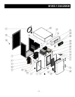
Page 17: ...15 MV85 1 DIAGRAM...

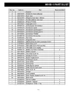
Page 18: ...16 MV85 1 PARTS LIST...

Page 19: ...17 MV85 2 DIAGRAM...

Page 20: ...18 MV85 2 PARTS LIST...

Page 21: ...19 MV85 3 DIAGRAM...

Page 22: ...20 MV85 3 PARTS LIST...

Reviews: