Multiplexing 201
Figure 9
-
3 Main page
Press the far right button to reset the counter display to zero.
Time and Date Indicator (optional)
A time and date indicator may be found on the upper left-hand side corner of the screen. The
availability of this indicator is based on the chassis on which the body is mounted. If the chassis
provides real-time clock information through J1939 bus, the time and date will appear on the screen.
To set the Time and Date indicator, go to the Main Menu and choose Time Adjust.
Hydraulic Oil Temperature Indicator (optional)
This optional indicator, when provided, shows you the current hydraulic oil temperature. This
indicator is found on the upper right-hand side corner of the screen.
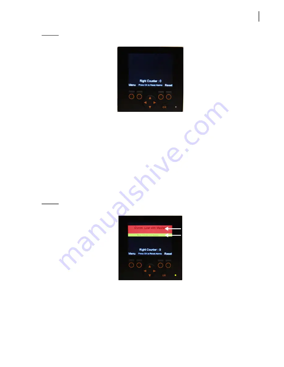
Warning and Caution Messages
On the monitor screen, yellow-highlighted messages indicate that caution should be used and red-
highlighted messages indicate a warning situation that must be dealt with quickly.
Figure 9
-
4 Warning and caution messages on monitor
See Table 1 for a list of warning and caution messages. Please note that this list is not exhaustive.
Summary of Contents for AUTOMIZER FULL EJECT
Page 1: ...AUTOMIZERTM FULL EJECT MAINTENANCE MANUAL ...
Page 2: ......
Page 3: ...AUTOMIZERTM FULL EJECT MAINTENANCE MANUAL ...
Page 36: ...28 Safety ...
Page 112: ...104 Lubrication ...
Page 139: ...Hydraulic System 131 Figure 5 23 Strainer assembly Strainer ...
Page 144: ...136 Hydraulic System Figure 5 27 Detecting cylinder internal leaks 1 2 3 4 5 A A A ...
Page 160: ...152 Hydraulic System 0 1 2345 62789 ELECTRO HYDRAULIC VALVE HD RH ARM ...
Page 161: ...Hydraulic System 153 0 1 2345 62789 ELECTRO HYDRAULIC VALVE CRUSHER PANEL HD RH ARM ...
Page 164: ...156 Hydraulic System ...
Page 176: ...168 Electric System Cab Console Control Wiring ...
Page 177: ...Electric System 169 Control Box ...
Page 178: ...170 Electric System Chassis ...
Page 179: ...Electric System 171 Tailgate Lighting ...
Page 180: ...172 Electric System Left Body SideWiring ...
Page 181: ...Electric System 173 Right Body Side Wiring ...
Page 182: ...174 Electric System Camera s Switchpack s Layout Option s AUTO 10 SEC INHIBIT AUTO ...
Page 204: ...196 Troubleshooting ...
Page 205: ...Troubleshooting 197 ...
Page 206: ...198 Troubleshooting ...
Page 230: ...222 Multiplexing ...
Page 254: ...246 Lifting Arm Figure 10 27 Standard lifting arm ...
Page 255: ...Lifting Arm 247 ...
Page 256: ...248 Lifting Arm ...


