Multiplexing 217
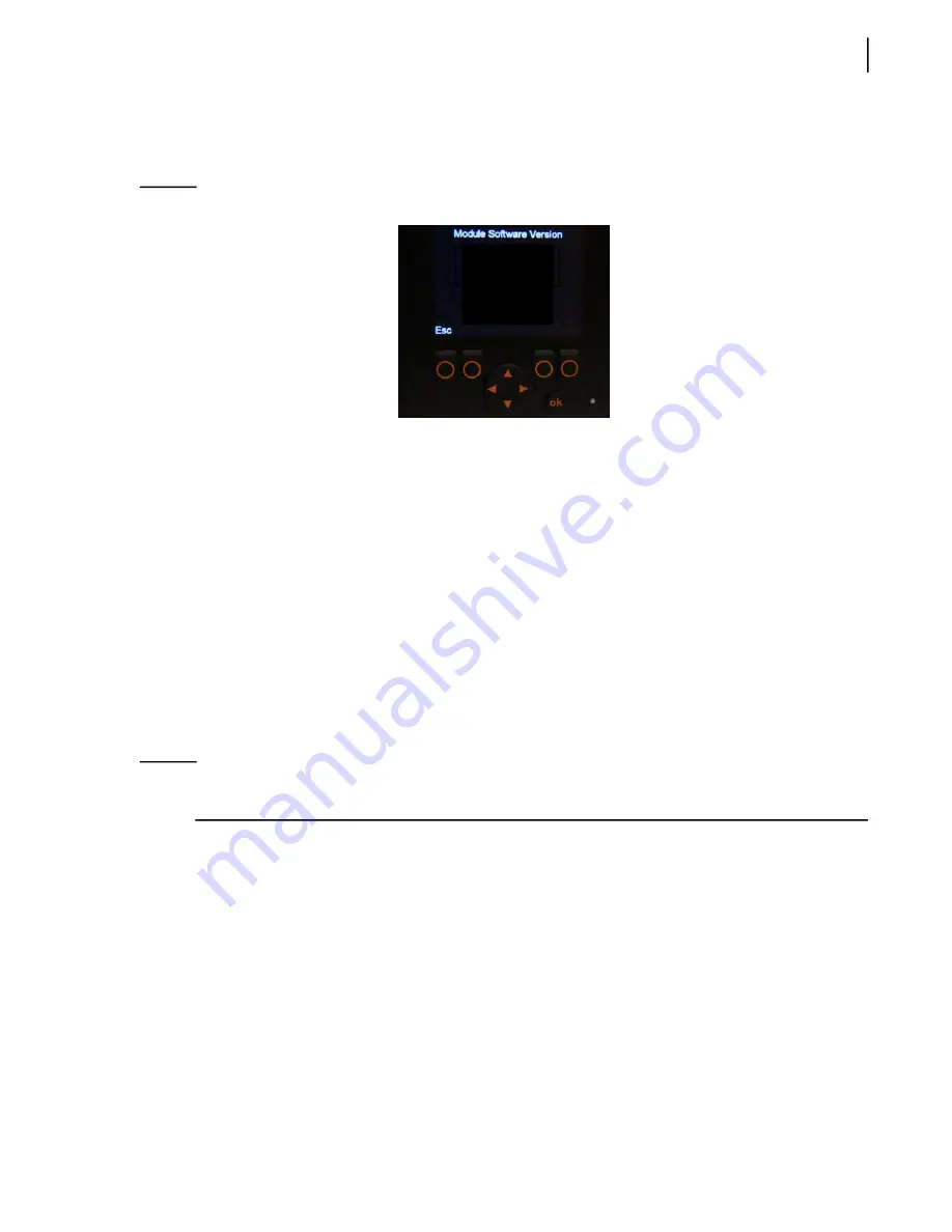
Module Software Version
On the Module Software Version page, you will find the software version currently used by each of
the modules installed on the truck and by the master control module.
Figure 9
-
17 Software version page
With the information on this page it is possible for the operator or maintenance personnel to
determine the electrical schematic number pertaining to a specific vehicle. Looking at Figure 9
above you will notice the following digit string 8-8-5-1 between, for example, 10 and R1. As all Labrie
electrical schematics begin with ZS00, you simply add those digits to that base number to get the
corresponding electrical schematic number. So, in this case, the electrical schematic number is
ZS008851.
Press “Esc” to return to the preceding page.
Pump Usage
This section contains an optional hour meter that tracks pump usage for maintenance purposes.
Press “Esc” to return to the preceding page.
Time Adjust
This section allows you to set the Time and Date indicator.
Press “Esc” to return to the preceding page.
N
OTE
:
To go back to the Main Page or Main Menu, press “Esc” as needed until the desired page is
displayed.
Warning Buzzer
Among the many buttons on the control panel you will find a warning buzzer (see Figure 9
18). This
buzzer sounds and a red light in its center flashes to warn the operator of any situation that might be
hazardous. When this happens, the operator can look at the monitor screen for more information on
the situation. A caution or warning message will be displayed. The buzzer also sounds when the truck
is in reverse or when the tailgate is being raised.
Module 10 = 10_8851_R1
Module 11 = 11_8851_R0
Module 50 = 50_8851_R0
Module 60 = 60_8851_R0
Summary of Contents for AUTOMIZER FULL EJECT
Page 1: ...AUTOMIZERTM FULL EJECT MAINTENANCE MANUAL ...
Page 2: ......
Page 3: ...AUTOMIZERTM FULL EJECT MAINTENANCE MANUAL ...
Page 36: ...28 Safety ...
Page 112: ...104 Lubrication ...
Page 139: ...Hydraulic System 131 Figure 5 23 Strainer assembly Strainer ...
Page 144: ...136 Hydraulic System Figure 5 27 Detecting cylinder internal leaks 1 2 3 4 5 A A A ...
Page 160: ...152 Hydraulic System 0 1 2345 62789 ELECTRO HYDRAULIC VALVE HD RH ARM ...
Page 161: ...Hydraulic System 153 0 1 2345 62789 ELECTRO HYDRAULIC VALVE CRUSHER PANEL HD RH ARM ...
Page 164: ...156 Hydraulic System ...
Page 176: ...168 Electric System Cab Console Control Wiring ...
Page 177: ...Electric System 169 Control Box ...
Page 178: ...170 Electric System Chassis ...
Page 179: ...Electric System 171 Tailgate Lighting ...
Page 180: ...172 Electric System Left Body SideWiring ...
Page 181: ...Electric System 173 Right Body Side Wiring ...
Page 182: ...174 Electric System Camera s Switchpack s Layout Option s AUTO 10 SEC INHIBIT AUTO ...
Page 204: ...196 Troubleshooting ...
Page 205: ...Troubleshooting 197 ...
Page 206: ...198 Troubleshooting ...
Page 230: ...222 Multiplexing ...
Page 254: ...246 Lifting Arm Figure 10 27 Standard lifting arm ...
Page 255: ...Lifting Arm 247 ...
Page 256: ...248 Lifting Arm ...


