background image

Hydraulic System 129

Emptying the Hydraulic Tank

To empty the hydraulic tank:

1.

Prepare the vehicle accordingly:

1 a.

Apply the parking brake.

1 b.

Start the engine.

1 c.

Engage the hydraulic pump.

1 d.

Retract all cylinders (packer, tailgate, etc.).

1 e.

Disengage the hydraulic pump.

1 f.

Stop the engine.

2.

Lock out and tag out the vehicle (see 

Locking Out and Tagging Out the Vehicle on page 26).

3.

Close the shut-off valve on the succion line (see Figure 2

-

13).

4.

Disconnect the succion line from the pump.

5.

Place a clean container (minimum capacity: 60 gallons) under the disconnected end of the 

succion line to empty the hydraulic tank.

6.

Open the shut-off valve to let the oil flow into the container.

7.

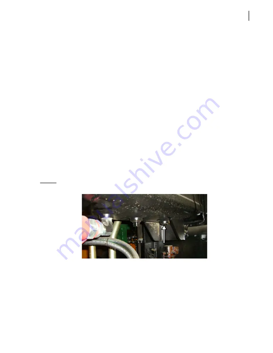
When the bulk of the oil has been emptied from the tank, remove the drain plug (see Figure 

5

-

21) to allow the rest of the oil drain from the tank.

Place a small container under the plug.

8.

Once the tank has been completely emptied, replace the drain plug and reconnect the succion 

line to the pump.

Figure 5

-

21      Drain plug

Cleaning the Strainer

To clean the strainer:

1.

Empty the hydraulic tank (see 

Emptying the Hydraulic Tank on page 129).

2.

Remove the hose clamp from the suction hose.

3.

Slide the hose over the pipe until it clears the nipple (slide towards the frame of the vehicle).

4.

Remove the strainer from the tank port (see Figure 5

-

22 and Figure 5

-

23).

Summary of Contents for AUTOMIZER FULL EJECT

Page 1: ...AUTOMIZERTM FULL EJECT MAINTENANCE MANUAL ...

Page 2: ......

Page 3: ...AUTOMIZERTM FULL EJECT MAINTENANCE MANUAL ...

Page 4: ...ion contained in this document All risks and damages incidental or otherwise arising from the use or misuse of the information contained herein are entirely the responsibility of the user Although careful precaution has been taken in the preparation of this document Labrie Enviroquip Group assumes no responsibility for errors or omissions September 2021 ...

Page 5: ...ns 8 Basic Safety Notions 9 Responsibilities 9 Employer s Responsibilities 9 Employee s Responsibilities 10 Things to Do 10 Things to Avoid 11 General Precautions 11 Hydraulics 14 Welding 14 Fire Protection 14 Housekeeping 15 Safety Features 16 Global Motion Sensors Optional 16 Back Up Alarm 18 Tailgate Safety Prop 18 Camera System optional 22 Tailgate Holding Valve 23 Prior to Start Up 24 Locking...

Page 6: ...witch 76 Adjusting Tailgate Unlocked Proximity Switch 78 Adjusting Tailgate Fully Open Proximity Switch 79 Adjusting Hopper Door Proximity Switch 81 Adjusting Arm Stowed Limit Switches 82 Adjusting Arm Mid Height Limit Switches 2 84 Adjusting Crusher Panel Up Limit Switch optional 85 Lubrication 87 Recommended Lubricants 87 Grease 87 Hydraulic Oil 88 Engine Oil 89 Transmission Oil 89 Testing Hydra...

Page 7: ...justing Pressure on the Proportional Valve 143 Adjusting Pressure on 96 Gallon Gripper 144 Adjusting High Pressure on 300 Gallon Gripper 145 Adjusting Low Pressure on 300 Gallon Gripper 147 Pressure and Cycle Time Charts 149 Main Hydraulic Schematics 151 Electric System 157 Electrical Schematics 157 How the Electrical System Works 157 Adjusting and Repairing Electric Components 159 Fuses and Circu...

Page 8: ...ick 218 Allison Transmission Parameters 219 Programmed Parameters 220 Cummins Engine Parameters 221 Lifting Arm 223 Daily Inspection 223 Gripper Auto Closing System 226 Inspecting Auto Closing System 227 Adjusting Auto Closing System 227 Auto Packing 229 Right Hand Arm Chain Tension and Gripper Position 230 Bleeding Air Out of the Lifting Arm Hydraulic Circuit 232 Lifting Arm Holding Valves 234 Ad...

Page 9: ...ccident prevention systems For these options refer to the appropriate manufacturer s service manual Operating the AUTOMIZER FULL EJECT For procedures related to the operation of the AUTOMIZER FULL EJECT please refer to the AUTOMIZER FULL EJECT Operator s Manual A copy of this manual is provided with the truck Parts and assemblies For parts and assemblies that make up the AUTOMIZER FULL EJECT andfo...

Page 10: ...he AUTOMIZER FULL EJECT has been developed based on years of experience and a wise choice of components Everything has been foreseen to achieve excellent reliability while keeping construction simple yet robust The AUTOMIZER FULL EJECT features a strong light weight body with a reliable loading arm called the RIGHT HAND arm This arm can reach positions of up to 12 feet from the hopper and lift up ...

Page 11: ...ing situation that must be dealt with quickly Figure 1 1 Monitor NOTE Maintenance personnel as well as in the field technicians who encounter any problems with the multiplexed system should refer to the Multiplex Diagnostic Manual part 153143_01 for troubleshooting information and guidelines Service and Maintenance on the AUTOMIZER FULL EJECT Maintenance on the AUTOMIZER FULL EJECT is of paramount...

Page 12: ...outine maintenance to ensure product longevity as well as dependability Various components have specific needs A detailed portion of these items is listed below 1 Lubrication Your AUTOMIZER FULL EJECT unit MUST BE COMPLETELY LUBRICATED before its first use All moving parts require lubrication for continued operation longevity and dependability Maintenance intervals should be adjusted according to ...

Page 13: ...and Proximity Switches Limit and proximity switches are used to limit travel of moving parts and or to ensure conditions are safe for operation If these switches are not adjusted properly damage to the equipment may occur as well as poor or dangerous functionality 6 Leaks Verify that there are not any leaking hydraulic cylinders hoses tubes valves or pumps Leaks in the hydraulic system are an indi...

Page 14: ...a Address 455 1st Avenue Levis QC G6W 5M6 Toll Free 1 877 452 2743 Customer Service Phone 1 877 452 2743 Service Fax 1 418 831 1673 Parts Fax 1 418 831 7561 Parts and warranty During business hours 8 00 AM to 5 00 PM Eastern Standard Time Technical Support Service Available 24 hours Website www labriegroup com E mail sales labriegroup com IMPORTANT For technical support and parts ordering the seri...

Page 15: ...njuries caused by repairs done by the user and or any persons other than authorized Labrie Enviroquip Group representatives Safety Decals Recognizing and understanding safety decals can prevent damage and could prevent injury or even death See the following recommendations regarding safety decals These decals must be obeyed at all times These decals must be in place at all times Report any damaged...

Page 16: ... WARNING and CAUTION notations accompanied by an exclamation mark inside a triangle an International Hazard Symbol are used to alert the operator and mechanics to special instructions concerning a particular operation or service that may be hazardous if performed incorrectly or carelessly Danger Indicates a hazardous situation which if not avoided will result in serious injury or death Warning Ind...

Page 17: ...ns including all safety requirements and codes set by the Occupational Safety and Health Administration OSHA and by the American National Standards Institute ANSI To ensure that employees are qualified for operating or maintaining the vehicle and its equipment and that they all take safety measures before working in on and around them To properly maintain all mobile equipment to meet all state pro...

Page 18: ...of a lockout tagout procedure see page 26 any time inspection repair or maintenance is performed on the vehicle regardless of whether it takes place on the road or in the garage Employee s Responsibilities It is the responsibility of the employee To enforce all safety measures to meet the requirements set by the employer To operate the AUTOMIZER FULL EJECT only after having received instructions a...

Page 19: ...rsonnel should service the hydraulic electrical and pneumatic systems of this vehicle They should also be knowledgeable about the operation of the vehicle General Precautions IMPORTANT It is the employer s responsibility to ensure that only qualified employees operate and maintain this vehicle Read and make sure that you fully understand this manual and all safety decals before performing maintena...

Page 20: ...y signs of damage or incomplete repairs Report any doubts that you might have and any safety service requirements regarding this vehicle to a supervisor Never place head body fingers or any limbs into a scissors point or pinch point on the equipment Start the engine following the manufacturer s recommended procedure When driving wear your seat belt Never drive this vehicle with the tailgate unlock...

Page 21: ...ntly cleared from the automated arm before moving it Failure to do so may result in unit and or property damages personal injury or death Warning Make sure there is enough clearance between raised container and overhead power lines The automated arm or the container must not come in direct contact with the electrical cables If the unit comes in contact with a power line stay in the cab and keep aw...

Page 22: ...must also inform their employees of an appropriate place near the maintenance facility to unload the body preferably away from traffic surface drains and ditches Keep a fire extinguisher accessible at all times Never use lighted smoking materials open flame or sparks around when working with flammable materials such as fuel tanks or storage batteries Caution Maintenance and repairs carried out on ...

Page 23: ...extinguishers and first aid kit Housekeeping Good housekeeping habits are a major factor in accident prevention Keep handrails and steps clean and free of grease or debris Rubbish scrap paper and litter are highly combustible Such material should be stored in metal containers entirely clear of sparks and flames Clean all lights and safety stickers so you and the surrounding pedestrians and drivers...

Page 24: ...en light on the cab control box should light up to indicate that the system is operating When an object is detected a yellow light comes on and an audible alarm is heard The vehicle brakes are automatically applied The brakes can be disabled by pressing the AUTO BRAKE OFF switch on the control box This will cause a red warning light to turn on indicating the brakes will not automatically engage Th...

Page 25: ...r to the Installation Manual of the sensor manufacturer Troubleshooting and Maintenance For information on troubleshooting and maintenance refer to the Troubleshooting Guide of Global Sensor Systems Inc Warning Sensor lenses must be kept clean to ensure proper operation of the system If the lenses are allowed to become dirty system range will be decreased ...

Page 26: ... sounds when the truck is in reverse or the tailgate is open Tailgate Safety Prop Setting the Tailgate Safety Prop The tailgate safety prop see Figure 2 3 is used to support and keep the tailgate open during inspection or maintenance procedures It is mandatory to set the safety prop each time the tailgate is open for such purposes ...

Page 27: ... 3 Tailgate safety prop To set the tailgate safety prop 1 Make sure that the body is empty 2 Remove the tailgate safety pins see Figure 2 4 Figure 2 4 Safety pin 3 Start the engine Danger The safety prop shall be set each time the tailgate is opened for inspection and maintenance purposes ...

Page 28: ...ILGATE DOWN switch on the in cab control panel see Figure 3 40 lower the tailgate onto the safety prop Putting theTailgate Safety Prop Back in Place To put the tailgate safety prop back in its home position 1 Start the engine 2 Turn ON the pump 3 With the TAILGATE UP switch on the in cab control panel raise the tailgate enough to move the safety prop freely 4 Raise the tailgate safety prop Danger ...

Page 29: ...on the safety prop to set it in its home position Figure 2 7 Setting the safety prop in its home position 6 With the TAILGATE DOWN switch on the in cab control panel fully close the tailgate The TAILGATE OPEN light indicator should turn off 7 Put the safety pins back in place ...

Page 30: ...e Figure 2 9 and one near the upper end of the right hand side front post see Figure 2 10 The operator can switch from one camera to the other using a selector switch located on the 7 LCD color monitor installed in the cab see Figure 2 11 Refer to the camera manufacturer s manual for more information Figure 2 8 Camera inside hopper Figure 2 9 Camera on tailgate ...

Page 31: ...post Figure 2 11 In cab LCD color monitor Tailgate HoldingValve Located under the rear section of the body this holding valve see Figure 2 12 ensures that the tailgate will not open during the packing cycle Figure 2 12 Tailgate holding valve ...

Page 32: ...n the suction line is fully open before starting the engine see Figure 2 13 Figure 2 13 Main shut off valve 3 Start the engine 4 Wait for the air pressure to build up to at least 70 psi Figure 2 14 Air pressure indicator Warning Failure to fully open the main valve will cause immediate damage to the pump even if the pump is turned off ...

Page 33: ...sure has reached 70 psi 5 Once the air pressure has reached 70 psi engage the hydraulic system by turning ON the Pump switch on the in cab control panel see Figure 2 15 Figure 2 15 Pump switch A green switch means the pump is active A blue switch means the pump is not active ...

Page 34: ...d 3 Switch OFF the hydraulic pump 4 Turn OFF the engine remove the key from the ignition store it in a safe and controlled area preferably on yourself and tape over the ignition switch 5 Turn OFF the master switch see Figure 2 17 IMPORTANT If the AUTOMIZER FULL EJECT is equipped with a master switch on the battery set you must turn it off This switch is offered as an option 6 Chock all wheels Figu...

Page 35: ...e requirements Also 1 Park the vehicle on hard level ground and apply the parking brake 2 Make sure that all moving parts are in their home position tailgate arm crusher panel packer etc 3 Turn OFF in sequence the hydraulic pump the electrical system the engine and the master switch 4 Drain all air tanks see Figure 2 18 Figure 2 18 Drain valve on air tank ...

Page 36: ...28 Safety ...

Page 37: ...ody unloading Use the provided hoe to rake debris out of the clean out doors see Figure 3 1 Make sure that the side step and or hopper step if installed are clean and free of any slippery material Figure 3 1 Clean out door Danger Always lock out and tag out the vehicle when inspecting or performing maintenance on the vehicle see Locking Out and Tagging Out the Vehicle on page 26 Caution Keep the c...

Page 38: ...cation chart on side of the vehicle X See page 98 Wiring System Check for damaged harnesses and or bad connections X See page 159 Battery Cables Ensure cables are not coming in contact with an area that could rub through the insulation X Operator controls Check for proper operation X Air tanks Drain X See page 175 Air system Check for leaks X See page 175 Safety systems Check for proper operation ...

Page 39: ...open X See page 105 Check on ground for overnight leaks X Check cylinders pump control valve and system for leaks Repair or replace if required X See page 105 Replace hydraulic filtera Twicea year See page 132 Clean strainer and refill X See page 129 Check pressure X See page 138 Hopper area Clean traps on each side X See page 29 Clean dirt around the packer X See page 29 Visual inspection Rollers...

Page 40: ...e recommends that operators perform daily inspection of the packer and its components Maintenance personnel must perform daily weekly inspection and maintenance greasing all moving parts daily Also proper adjustment of the limit and proximity switches is mandatory especially on vehicles equipped with the multicycle feature For information on lubrication see Lubrication on page 87 Any problems foun...

Page 41: ...intenance procedures are similar for each variation but there are a few key differences that will be explained below Variation 1 The packer panel and hopper floor are fitted with guide rails and wear shoes The body floor is curved with a center guide that runs the full length of the body floor to support the packer during the full eject sequence Figure 3 4 Packer variation 1 Rollers Side rail Foll...

Page 42: ...pper and body floor incorporate a trough design The packer panel has wear shoes mounted on the bottom and sides to guide the packer in the trough The wear shoes ride directly on the trough floor in this variation Figure 3 5 Packer variation 2 ...

Page 43: ...e packer while packing and during the full eject sequence A trolley assembly is bolted to the bottom of the packer that rides on the T Track Additional wear shoes were added to the sides of the packer that ride on wear strips or liner if equipped on the upper shelf portions of the floor Figure 3 6 Packer variation 3 ...

Page 44: ...Fully extend the packer by pressing the green PACK button on the packer control station see Figure 3 23 6 When the packer has reached its fully extended position press the red EMERGENCY STOP button on the packer control station see Figure 3 25 7 Place the tailgate safety prop into service position 8 Perform the lockout tagout procedure see Locking Out and Tagging Out the Vehicle on page 26 Danger ...

Page 45: ...s need to be replaced when damaged or when showing excessive wear or flat spots Seized rollers will eventually wear through the side channel radius which leads to costly repairs Figure 3 8 Follower panel rollers 3 Inspect the floating panel scraper This scraper acts as additional protection against intruding refuse that may get behind the packer where they can damage the cylinder and the limit swi...

Page 46: ... itself There should not be leaks on the hoses and pipes Figure 3 10 Telescopic cylinder 5 Inspect packer front scrapers These scrapers are used to prevent refuse from getting behind the packer where they can damage the cylinder and the limit switches The minimum gap between the front scrapers and the hopper should be 1 16 If gap is excessive over the scrapers should be replaced Scrapers that are ...

Page 47: ...of the packer Variation 1 i With a pry bar try to move the packer vertically up and down motion and horizontally side to side motion It should not move vertically by more than 3 16 and horizontally by more than 1 8 If movement is greater than the values indicated above check for excessive wear on both packer sliding shoes and on the wear pads under the side rails ...

Page 48: ...pper packer guides and top of side rails If gap is less than 3 8 replace the packer bottom wear plates ii Check gap between side wear plates and side of trough Minimum gap should be 1 8 per side overall and maximum gap should be per side overall If gap is more than per side replace or shim the side wear plates Figure 3 13 Variation 2 1 3 16 Max 1 8 Max See Fig 3 15 See Fig 3 14 ...

Page 49: ...er packer guides and top of side rails If gap is less than 3 8 replace the packer bottom wear plates If wear plates on central trolley are worn the central trolley assembly should be replaced ii Check the thickness of the two sliding shoes one on each side of the packer If any of the two rear front bolt on parts are getting too close to the metal surface of the track the sliding shoe s should be r...

Page 50: ...ly to prevent further damage to the packer a Inspect all welds for wear and or cracks where the cap is attached to the tunnel If welds are worn or cracked they should be ground out and re welded b Inspect the bend radius on the top and both sides of the tunnel for wear and or cracks If cracked or worn through the tunnel will need a wear plate overlay installed T Track Central Trolley ...

Page 51: ... lb d Check cylinder pin retainer and hardware for wear Figure 3 18 Tunnel assembly 2 Tunnel wear plate overlay kits have been created for packer variations 2 and 3 These kits were created from Hardox 450 to extend the life of the packer tunnel by increasing the wear resistance Tunnel cap welds Tunnel bend radius Cylinder pin retainer Centraltrolley hardware ...

Page 52: ... 2 Figure 3 19 Service kit SERV02820 SERV02831 fits packer variation 3 T Track Figure 3 20 Service kit SERV02831 Contact your LabriePlus Field Service Representative If you have any questions regarding the installation of the tunnel wear plate overlay kits ...

Page 53: ... the engine and engage the hydraulic system PUMP switch set to ON Wait for the air pressure to reach 70 psi before engaging the hydraulic system 3 Remove the tailgate safety pins see Figure 3 21 and fully open the tailgate by pressing the TAILGATE UP switch on the in cab control panel see Figure 3 22 Keep the TAILGATE UP switch pressed until the tailgate is fully open Figure 3 21 Safety pin ...

Page 54: ...ss the green PACK button to fully extend the packer see Figure 3 23 When the packer has reached its fully extended position see Figure 3 24 press the red EMERGENCY STOP button to stop the packer see Figure 3 25 Figure 3 23 Pack button Danger Never enter the hopper while the packer is moving ...

Page 55: ...he body and under the follower panels place a piece of wood under the telescopic cylinder to ensure it does not move once the cylinder pin is removed from the tip of the tunnel see Figure 3 26 7 Exit the body 8 At the rear of the truck remove the tunnel cap see Figure 3 26 to have access to the front end of the telescopic cylinder 9 Remove the bolt securing the pin cover to the center tunnel see F...

Page 56: ...yellow PACKER RETRACT button to retract the cylinder see Figure 3 28 14 Proceed with the tagout lockout procedure Refer to Locking Out and Tagging Out the Vehicle on page 26 15 Install any safe lifting device and hook the packer by the lifting ring see Figure 3 26 16 Pull the packer out of the side rails and out of the T Track see Figure 3 29 and place it in a safe work area NOTE When pulling out ...

Page 57: ...s worn out you must replace it to achieve packer optimal performance To replace a worn or damaged central trolley proceed this way 1 Remove the packer from the body See Removing the Packer on page 45 2 Once the packer is placed in a safe work area remove the central trolley To do so unscrew all 16 bolts that hold the trolley to the central tunnel Warning When you pull out the packer always ensure ...

Page 58: ... signs of excessive wear These may include but are not limited to bent torn or scratched In such a situation the replacement of the T Track is required for optimum performance of the packer It will help the packer to move more smoothly with less sideway and or up and down motions To replace the T Track do the following 1 Remove the packer from the body See Removing the Packer on page 45 2 Remove t...

Page 59: ...as been properly installed Replacing Sliding Shoes If one or both sliding shoes need to be replaced because they are thinned out so much that there isn t much protective material left on the main contact surface between the packer and the elevated body floor apply the following procedure To replace the sliding shoes METHOD A The packer is inside the waste body 1 Ensure the parking brake is applied...

Page 60: ...er upper bolts see Figure 3 32 Put aside the plate and the bolts Figure 3 32 Rear sliding shoe plate 7 c On the front side of the packer remove the tack welds and the 3 bolts that secure the adjustable plate to the packer see Figure 3 33 Figure 3 33 Front sliding shoe plate 7 d Through the sump box push on the sliding shoe using a hammer and a large screwdriver or a similar tool to get it out of t...

Page 61: ...e is fully open 12 Run the packer for a few cycles to ensure it moves properly 13 Once done press the yellow PACKER RETRACT button to retract the packer see Figure 3 28 14 Proceed with the tagout lockout procedure Refer to Locking Out and Tagging Out the Vehicle on page 26 15 If need be adjust the position of the plates for optimum performance of the sliding shoe Move up or down the adjustable pla...

Page 62: ...4 If the other sliding shoe must also be replaced repeat steps 2 and 3 5 Reinstall the packer inside the body see Reinstalling the Packer on page 55 6 Once this task is complete start the engine and engage the hydraulic system Wait for the air pressure to reach 70 psi before engaging the hydraulic system 7 Run the packer for a few cycles to ensure it moves properly 8 Once done press the yellow PAC...

Page 63: ...see Figure 3 26 NOTE When reinstalling the packer into the body the follower panels must also be properly supported Proceed slowly and with great care 4 Lift the packer and align the rollers of the follower panels see Figure 3 35 with the side rails inside the body Figure 3 35 Rollers 5 Push the follower panels in slowly 6 Once all the rollers of the follower panels have been inserted in the side ...

Page 64: ...to the tip of the packer tunnel 10 When the cylinder eye end is aligned with the side holes of the tunnel tip press the red EMERGENCY STOP button see Figure 3 25 11 Proceed with the tagout lockout procedure Refer to Locking Out and Tagging Out the Vehicle on page 26 12 Secure the cylinder front end with the pin see Figure 3 27 Figure 3 37 Packer tunnel hole packer turned upside down 13 Put the bol...

Page 65: ... to retract the packer to its home position see Figure 3 38 Figure 3 38 Packer Retract button 18 Extend and retract the packer in EJECT mode for a full cycle to make sure the packer has been properly installed To activate this mode press and hold the AUTO EJECT switch on the in cab control panel see Figure 3 39 Figure 3 39 Auto eject switch Caution Make sure the ball valve on the suction line is f...

Page 66: ...n the following sections Removing the Packer Telescopic Cylinder The procedure below details how to remove the telescopic cylinder for replacement purposes To remove the cylinder 1 Ensure the parking brake is applied 2 Remove the tailgate safety pins see Figure 3 21 3 Start the engine and engage the hydraulic system Wait for the air pressure to reach 70 psi before engaging the hydraulic system 4 F...

Page 67: ...ring the pin cover to the center tunnel see Figure 3 26 12 Remove the pin cover see Figure 3 41 13 Remove the cylinder pin see Figure 3 41 Figure 3 41 Pin cover and cylinder pin 14 Start the engine and engage the hydraulic system PUMP switch set to ON Wait for the air pressure to reach 70 psi before engaging the hydraulic system 15 On the packer control station press the yellow PACKER RETRACT butt...

Page 68: ...ess cover to access the parts inside see Figure 3 44 21 Disconnect both hydraulic hoses from the cylinder Use absorbent material to catch oil spills 22 Disconnect the greasing hose from the cylinder 23 Remove both pin plates one on each side of the beam see Figure 3 43 24 Remove the pin that holds the telescopic cylinder in place see Figure 3 44 Lifting rings Access cover removed Pin plate Cylinde...

Page 69: ...Make sure the truck is properly locked out and tagged out see Locking Out and Tagging Out the Vehicle on page 26 2 With an appropriate lifting device carefully lower the cylinder rear end first into the body through the hopper 3 Move the cylinder towards the front of the body Be sure to position the rear end of the cylinder towards the front end of the body The rear end of the cylinder must be ins...

Page 70: ...ine and engage the hydraulic system PUMP switch set to ON Wait for the air pressure to reach 70 psi before engaging the hydraulic system 12 On the packer control station press the green PACK button see Figure 3 23 to fully extend the packer cylinder Be careful when the cylinder reaches the packer its front end must go inside the packer through the tunnel hole see Figure 3 37 up to the tip of the p...

Page 71: ...ts home position 23 Close the tailgate completely by pressing and holding down the TAILGATE DOWN switch on the in cab control panel see Figure 3 40 Panel Scraper Replacing the Panel Scraper To replace the panel scraper on an AUTOMIZER FULL EJECT unit apply the following procedure 1 Start the engine and engage the hydraulic pump Wait for the air pressure to reach 70 psi before engaging the hydrauli...

Page 72: ... do so pull the panel spring loaded latch to the right then pull the floating panel wide open Figure 3 45 Floating panel 7 Remove the retaining screws holding the panel scraper in place see Figure 3 46 Figure 3 46 Retaining screws holding panel scraper Warning Keep hands and fingers away from the pinch point of the floating panel Spring loaded latch panel scraper Floating panel Scraper Retaining s...

Page 73: ...performed by 2 people To replace the packer roller assemblies 1 Ensure the parking brake is applied 2 Start the engine and engage the hydraulic system Wait for the air pressure to reach 70 psi before engaging the hydraulic system 3 Remove the tailgate safety pins see Figure 3 21 and fully open the tailgate by pressing the TAILGATE UP switch on the multiplexed control panel see Figure 3 22 Keep the...

Page 74: ...olts to be removed 8 b Remove the roller assembly and replace it with a new one 8 c Put back all 4 bolts in their respective holes before tightening them up 9 Remove the right hand side roller of the first panel and replace it by repeating Step 8 Move the woodblock to the other side under the panel 10 Place the 2 by 4 woodblock under the second panel long enough to hold the panel in place once the...

Page 75: ...cycle to check for proper operation Replacing Rollers If the roller itself has to be replaced because of wear apply the following procedure 1 Once the roller has been removed from the follower panel see Packer Roller Assemblies on page 65 remove the external snap ring Figure 3 49 Removing external snap ring 2 Remove the washer Figure 3 50 Removing washer 3 Slide out the roller 4 Reverse the previo...

Page 76: ... pins are parts of the tailgate that should particularly be looked at in search of any type of wear or metal fatigue Tailgate rubber seal should also be looked at for signs of wear or damage that may hinder its effectiveness Always replace the parts that are faulty Figure 3 51 Tailgate NOTE The image shown above is indicative only and may differ from actual truck appearance Tailgate Cylinder Rubbe...

Page 77: ...itches on streetside of truck Warning Proximity and limit switches must function properly Serious damage to the equipment injuries or death may occur if you operate the machinery with improperly adjusted switches Crusher panel limit switch optional Hopper door proximity switch Arm stowed limit switch Arm mid height limit switches Packer extend retract prox limit switches Arm stowed limit switch Pa...

Page 78: ...closed This may cause an accident injuries or property damages To adjust a limit switch 1 Loosen the limit switch nut 2 Move the rod to the approximate position where the switch is to be triggered 3 Tighten the nut 4 To fine tune the adjustment loosen the nut slightly 5 With a flathead screwdriver turn the adjusting screw located at the center of the nut until a click is heard 6 Tighten the nut 7 ...

Page 79: ...y extending and retracting to the end of their strokes On some units the packer range of motion is controlled by two limit switches and on other units it is controlled by a set of one limit switch and one proximity switch The limit proximity switch that stops the packer during extension packer extend is located on the curbside front lower section of the body see Figure 3 54 and Figure 3 55 The lim...

Page 80: ...tenance Figure 3 54 2 limit switch set up Figure 3 55 1 limit proximity switch set up Packer extend limit switch Packer retract limit switch Target Rod Packer retract limit switch Packer extend prox switch Target Rod ...

Page 81: ... Auto Eject switch the packer will stop moving 4 Turn OFF the engine 5 Proceed with the tagout lockout procedure Refer to Locking Out and Tagging Out the Vehicle on page 26 6 Get on the hopper area 7 Free the limit switch from any dirt or debris that may cause the switch to malfunction 8 Exit the hopper 9 Start the engine and engage the hydraulic system PUMP switch activated 10 Press the yellow PA...

Page 82: ...packer extend proximity switch 1 Set the parking brake 2 Start the engine and engage the hydraulic system PUMP switch activated Usually the packer extend proximity switch needs adjustment when the last follower panel moves past the switch without triggering any signal In such a case the packer continues its forward motion inside the body as in Eject mode 3 Press and hold the Auto Eject switch on t...

Page 83: ...to stop retraction at such position 11 Turn OFF the engine 12 Proceed with the tagout lockout procedure Refer to Locking Out and Tagging Out the Vehicle on page 26 13 Adjust the Packer Extend proximity switch To do so 13 a Loosen the nuts of the proximity switch bracket 13 b Move the bracket so that a gap of 1 is reached between the switch and the target 13 c Once you have determined the contact p...

Page 84: ...tic cycles from working properly A well adjusted Packer Retract limit switch should prevent the packer from making a knocking noise when it stops during retraction in speed up mode When this limit switch needs adjustment the following procedure is recommended To adjust the Packer Retract limit switch 1 Set the parking brake 2 Start the engine and engage the hydraulic system PUMP switch activated 3...

Page 85: ...y to loosen the locknut on the limit switch and determine the contact point where the triggering should occur by moving the rod 9 Once you have determined the contact point where the triggering should occur retighten the locknut 10 Start the engine and engage the hydraulic system PUMP switch activated 11 Fully retract the packer and press the green PACK button to start a complete cycle and test th...

Page 86: ...itch2 When the switch is triggered the warning buzzer and backup alarm stop sounding the TAILGATE UNLOCKED warning light turns off and packing operation can resume However some troubles may occur if the tailgate unlocked proximity switch is out of adjustment For example the tailgate is locked but the in cab buzzer is still sounding or the TAILGATE UNLOCKED warning light is off while the tailgate i...

Page 87: ... the warning buzzer and backup alarm start sounding after you press the switch 5 Repeat the procedure if need be AdjustingTailgate Fully Open Proximity Switch The AUTOMIZER FULL EJECT has a feature that allows the operator to unload all the refuse collected during his run with the press of a single switch This feature is called Auto Eject mode And for this feature to work correctly the tailgate fu...

Page 88: ...is on the body streetside near the tailgate hinge To adjust the tailgate fully open proximity switch 1 Fully open the tailgate see Figure 3 62 Figure 3 62 Tailgate fully open Warning Ensure that no one is standing behind or near the tailgate when the adjustment procedure is carried out ...

Page 89: ...n the switch light should be off 4 Repeat the procedure until the proximity switch is properly adjusted Adjusting Hopper Door Proximity Switch This proximity switch see Figure 3 63 turns off all hydraulic power when the hopper door is not closed Figure 3 63 Hopper door proximity switch under protective cover This switch is located on the lower side door frame behind its protective cover Figure 3 6...

Page 90: ... adjustment procedure 7 Once the proper adjustment is achieved reinstall the protective cover and secure it using the two remaining bolts NOTE The automated arm must be extended in order to open the hopper door and do the test Adjusting Arm Stowed Limit Switches The Arm Stowed limit switches illuminate the ARM OUT warning lights on the dashboard see Figure 3 67 when the operator extends the arm or...

Page 91: ... will trigger the limit switch click sound and turn off the warning lights For the ARM OUT warning lights to stop flashing both limit switches may require to be adjusted Figure 3 66 Limit switch 3 c Retighten the nut 4 Slightly close the gripper or extend the arm out about 1 inch The ARM OUT warning lights should start flashing 5 Repeat the procedure until the limit switches are properly adjusted ...

Page 92: ... gripper to open when the arm is lower than the mid height sensor and activates the gripper automatic close function gripper auto close when arm is higher than the sensor The higher switch is used as a trigger for the camera auto switching function when there are cameras on the right hand wall and inside the hopper The arm mid height limit switches are located on the side of the arm ...

Page 93: ...d down movement of the arm The roller levers should be centered on the target Figure 3 68 Roller lever Adjusting Crusher Panel Up Limit Switch optional The crusher panel up limit switch see Figure 3 69 disables the arm operation when the crusher panel is not in its stowed position and redirects the arm power to the crusher panel up function when the deadman switch on the arm joystick is activated ...

Page 94: ...age 26 4 Enter the hopper 5 Adjust the crusher panel up limit switch so that it is triggered when the crusher panel is in the up position 6 Exit the hopper and enter the cab 7 Start the truck and engage the hydraulic pump 8 Fully raise the crusher panel using the CRUSHER PANEL UP switch on the in cab control panel 9 Using the joystick try to move the automated arm The arm should move NOTE Do not f...

Page 95: ... understand that providing the proper amount of grease is a delicate balance between over greasing which can result in seal damage as well as wasted lubricant Only pump enough grease until the air purges from the joint Commonly a popping sound can be heard as the old grease begins to evacuate the seal Equally important is to remove the excess grease from the component you are maintaining Leaving t...

Page 96: ...lure to maintain hydraulic cleanliness to recommended guidelines may result in failure of hydraulic components and void your warranty Oil Recommendations All Labrie hydraulic systems are filled at the factory with a high quality anti wear hydraulic fluid meeting an ISO 32 specification On vehicles that are used in high ambient temperatures or that sustain high duty cycles it may be desirable to ch...

Page 97: ...nt oil by other manufacturers may also meet your application requirements The oil identification tag is located on the hydraulic tank Replacement decals may be ordered from the Labrie Parts Department Figure 4 1 Example of an oil identification tag Engine Oil Refer to the engine manufacturer s maintenance manual for recommended type of engine oil Transmission Oil Refer to the transmission manufact...

Page 98: ...he body onto it 5 Disengage the pump and turn OFF the engine 6 Locate the oil sample coupler along the right hand side chassis frame rail It is located behind the filter cover see Figure 4 2 Figure 4 2 Oil sample coupler 7 Remove the cap from the sample coupler and clean the coupler with a clean rag 8 Push on the coupler spring ball see Figure 4 3 using a small tip to purge oil before taking a sam...

Page 99: ...le To do so 1 Remove the sample kit from its bag and using a screwdriver remove the vent cap from the bottle cap see Figure 4 4 Figure 4 4 Vent cap 2 Remove the protective cap from the probe Figure 4 5 Probe cap and tip 3 Install the probe on the coupler to fill the sample bottle Use an EMA coupler with M16 2 0 threads Tip Cap ...

Page 100: ...to do this Remove excess oil through the vent DO NOT OPEN THE BOTTLE Figure 4 7 Recommended oil level 5 Once the sample is taken remove the probe from the coupler and pull out the probe to remove it from the bottle see Figure 4 8 Figure 4 8 Pulling out probe from bottle 6 Put the seal cover over the bottle cap Probe ...

Page 101: ...le see Figure 4 10 Figure 4 10 Identification form sticker Lubrication Charts Lubrication charts in this manual may differ from the ones displayed on the vehicles For lubrication specifications always refer to the charts on the vehicles Figure 4 11 Lubrication charts on an AUTOMIZER FULL EJECT vehicle Sealed sample ...

Page 102: ... HAND lifting arms are found at the end of chapter 10 Caution Never grease the side rails and the outside of rollers Sand and other abrasives stick to grease which may cause premature component wear Caution Because of their intensive use the packer and its accessories must be lubricated every working day ...

Page 103: ...inder heads every week by using the grease fittings 2 Grease the crusher panel bushings every week 3 Grease the grease fittings on the lower tube rings every week see Figure 4 14 Figure 4 13 Grease areas Figure 4 14 Grease fittings on lower tube rings Cylinder axle Cylinder head Grease fittings Bushings Cylinder axle ...

Page 104: ...echanism and Cylinder Pins It is important to lubricate the tailgate hinges locking mechanism and the cylinder pins every week with multipurpose grease see Recommended Lubricants on page 87 Also inspect the welds around hinges The proper working condition of the following components is also to be checked Tailgate hydraulic cylinders Danger Do not operate this equipment if there are any signs of da...

Page 105: ... on locking mechanism Wear on tailgate lock pins Tailgate rubber seal Figure 4 16 Grease fittings Tailgate hinge and cylinder Figure 4 17 Tailgate locking mechanism Danger Do not operate this equipment if there are any signs of damage or incomplete repairs Locking pin Safety pin ...

Page 106: ...roceed with the LOTO procedure See Locking Out and Tagging Out the Vehicle on page 26 4 Underneath the center tunnel locate the grease fitting of the cylinder front pin see Figure 4 18 5 Apply lubricant Figure 4 18 Access to front pin grease fitting To lubricate the packer cylinder rear pin 1 Disengage the hydraulic pump and turn OFF the engine 2 Proceed with the LOTO procedure See Locking Out and...

Page 107: ...20 Only the right hand side panel rollers are visible The left hand side ones are not visible or accessible when the packer is completely retracted 5 Proceed with the lubrication of the upper panel rollers 5 a Locate the grease fitting of the right hand side roller see Figure 4 21 5 b Apply lubricant with a grease gun 5 c Locate the remote grease fitting for the left hand side roller see Figure 4 ...

Page 108: ...ngage the hydraulic pump and turn OFF the engine 3 Proceed with the LOTO procedure See Locking Out and Tagging Out the Vehicle on page 26 4 Through the sump box see Figure 3 34 locate the two T Track lube fittings see Figure 4 22 5 Apply lubricant with a grease gun Upper roller assembly Middleroller assembly Lower roller assembly Roller grease fitting Remote grease fitting ...

Page 109: ...page 87 To lubricate the hopper door hinges 1 Disengage the hydraulic pump and turn OFF the engine 2 Proceed with the LOTO procedure See Locking Out and Tagging Out the Vehicle on page 26 3 Locate the grease fitting on each door hinge see Figure 4 23 The AUTOMIZER FULL EJECT hopper door has two 2 hinges 4 Apply lubricant with a grease gun Figure 4 23 Grease fittings on hopper door hinges Rear of p...

Page 110: ...ery week with multipurpose grease see Recommended Lubricants on page 87 To lubricate the sump box hinges 1 Disengage the hydraulic pump and turn OFF the engine 2 Proceed with the LOTO procedure See Locking Out and Tagging Out the Vehicle on page 26 3 Locate the grease fitting on each sump box hinge see Figure 4 24 4 Apply lubricant with a grease gun Figure 4 24 Sump box hinges Grease fittings Grea...

Page 111: ...or see Recommended Lubricants on page 87 To lubricate the hopper side walls and the hopper floor 1 Fully retract the packer 2 Disengage the hydraulic pump and turn OFF the engine 3 Proceed with the LOTO procedure See Locking Out and Tagging Out the Vehicle on page 26 4 With a grease gun apply grease on the hopper side walls and the hopper floor see Figure 4 25 Figure 4 25 Hopper side walls floor N...

Page 112: ...104 Lubrication ...

Page 113: ...e following care must be taken Every day check that hydraulic lines and connections are not leaking Correct if necessary Inspect the pump for leaks or unusual noise When maintenance is carried out protect all hoses fittings pipes or any other ingress points from dirt that would eventually get into the oil Plug hoses that are not connected Danger Always lock out and tag out the vehicle see Locking ...

Page 114: ...t off valve on the hydraulic tank see Figure 2 13 must be completely open before engaging the pump or starting the engine Labrie Enviroquip Group requires that the hydraulic fluid and return oil filter be changed and that the strainer be cleaned before changing the hydraulic pump Manufacturer s warranty on hydraulic pumps provided or sold by Labrie Enviroquip Group could be declared void if the hy...

Page 115: ...eir home position retract the packer close the tailgate etc NOTE The home position is where there is little or no hydraulic oil in the cylinders which are completely retracted Most of the oil has flowed back into the tank 4 Disengage the pump and turn OFF the engine 5 Use a folding stepladder to gain visual access to the oil gauge located on the hydraulic tank 6 Inspect the oil through the gauge I...

Page 116: ... vane pump known as the body vane pump located closer to the pump shaft powers all body functions tailgate and packer through the directional control valve see next section It is capable of delivering a flow of 24 5 gallons per minute gpm at 700 rpm A dump valve located on the bottom center of the body near the main valve see Figure 5 2 limits the flow to the valve to 60 gpm All excess flow is sen...

Page 117: ... body functions tailgate and packer Figure 5 3 Directional control valve Tailgate 4 ways 3 positions Packer 4 ways 3 positions NOTE All sections are electro hydraulically actuated For more information on the directional control valve see Main Hydraulic Schematics on page 151 To learn how to adjust hydraulic pressure see Hydraulic Pressures on page 138 Packer section Tailgate section ...

Page 118: ...extends and retracts Each section of this valve is actuated by an electric coil located on the side of the valve Figure 5 4 Proportional valve Input output cover provided with main relief valve Gripper section open close not proportional with load sensor relief Lifting arm section extend retract proportional no load sensor relief Lifting arm section up down proportional no load sensor relief Inspe...

Page 119: ...g with the replacement of the pump determine the type of pump setup that is used on your AUTOMIZER FULL EJECT unit There are 3 types of pump setups front mounted PTO driven mounted pump connected to PTO via a drive shaft and direct mount PTO Basically each setup calls for the same replacement method but with some differences due to the position of the pump A To replace a front mounted hydraulic pu...

Page 120: ...urize the tank If tank is of the pressurized type Figure 5 6 Breather cap 5 Remove the cab grill Figure 5 7 Cab grill 6 Disconnect the electric coil on the dump valve see Figure 5 8 Caution Always loosen the breather cap slowly to let the internal air pressure dissipate in order to avoid serious injury ...

Page 121: ...sually but not necessarily located atop the pump NOTE Always reinstall the dump valve and its components shims block assembly as they were before uninstallation Make sure you do not invert them Figure 5 9 Dump valve 9 Remove the suction block see Figure 5 10 and save it for the new pump Caution Before disconnecting hydraulic hoses from the pump place a pan under it to catch oil that may drip down ...

Page 122: ...ort 12 Remove the pump If need be disconnect the drive shaft from the pump and save it for the replacement pump 13 Install the new pump Before attempting to install the new pump it is very important to check the port configuration on that pump the ports on the replacement pump must be positioned the same way as on the old pump If they are not proceed with the indexing of the new pump The replaceme...

Page 123: ...ut the pump on a flat surface or in a vise BODY SECTION 13 b Remove all 4 retaining bolts that hold the mounting cap in place NOTE You may leave two retaining bolts partially unscrewed to facilitate rotation with a metallic bar 13 c Rotate the mounting cap accordingly ...

Page 124: ...rt NOTE The cartridge will rotate with the housing IMPORTANT Be sure not to pull on the mounting cap Otherwise the dowel pin may leave its position in the housing causing damage to the pump 13 d Put all 4 bolts back in place 13 e Check if the shaft rotates freely 13 f Tighten up all bolts to the torque of 138 140 ft lb When tightening bolts be sure to respect the following number sequence to avoid...

Page 125: ...E You may leave two retaining bolts partially unscrewed to facilitate rotation with a metallic bar 13 h Rotate the front cap accordingly Rotation can be done by turning the front cap clockwise or counter clockwise with your hands or by using a metallic bar NOTE Make sure pump does not come apart 1 2 3 4 ...

Page 126: ...pect the following number sequence to avoid damaging the seals 14 Reinstall the drive shaft if it has been removed from the engine Before proceeding with the installation of the drive shaft apply the following procedure 14 a On the drive shaft mark the location where a hole must be drilled Use the yoke as a jig to determine where exactly the hole must be drilled then remove it NOTE The yoke must b...

Page 127: ...cure the pump to the plate 17 Go through Steps 5 to 9 in reverse order to reinstall the various components of the pump assembly 18 Fill the pump housing with new oil 19 Retighten the breather cap if applicable 20 Open the shut off valve see Figure 2 13 21 Prime the new pump see Priming a New Pump on page 126 22 Put the cab grill back on see Figure 5 7 NOTE Labrie Enviroquip Group strongly recommen...

Page 128: ...unscrew all hydraulic hoses 4 that are attached to the pump 7 Remove the dump valve if equipped NOTE The dump valve is usually but not necessarily located atop the pump NOTE Always reinstall the dump valve and its components shims block assembly as they were before uninstallation Make sure you do not invert them 8 Remove the suction block see Figure 5 12 and save it for the new pump Figure 5 12 Su...

Page 129: ... facilitate reconnection to the hydraulic system and attachment to the chassis frame Go to page 115 to know how to index the new pump procedure begins with Step 13 a 13 Reinstall the drive shaft if it has been removed from the engine Before proceeding with the installation of the drive shaft apply the following procedure 13 a On the drive shaft mark the location where a hole must be drilled Use th...

Page 130: ...ng Hydraulic Oil on page 133 C To replace a direct mount PTO apply the following procedure 1 Disengage the pump and turn OFF the engine 2 Make sure the parking brake is applied and the vehicle is tagged out for maintenance purposes refer to Locking Out and Tagging Out the Vehicle on page 26 3 Close the shut off valve see Figure 2 13 4 Slowly loosen the breather cap on the hydraulic tank to depress...

Page 131: ...emove the pump 11 Install the new pump using a suitable lifting device Before attempting to install the new pump it is very important to check the port configuration on that pump the ports on the replacement pump must be positioned the same way as on the old pump If they are not proceed with the indexing of the new pump The replacement pump must be oriented in such a way to facilitate reconnection...

Page 132: ... Fill the pump housing with new oil 16 Retighten the breather cap if applicable 17 Open the shut off valve see Figure 2 13 18 Prime the new pump see Priming a New Pump on page 126 NOTE Labrie Enviroquip Group strongly recommends you change the filter element and the hydraulic oil as well as clean the hydraulic tank before starting a new pump see Replacing Filter Elements on page 132 and Replacing ...

Page 133: ...n the drive shaft see illustration below 2 Place the yoke on the shaft as illustrated above The yoke must be fully engaged on the shaft with both holes aligned one hole over the other 3 Apply Loctite 243 medium strength to bolt threads and insert the bolt firmly into the holes to properly secure the yoke to the shaft 4 Install a steel wire on the yoke bolt the wire must be fixed tight around the b...

Page 134: ...ut and Tagging Out the Vehicle on page 26 2 With the shut off valve closed see Figure 2 13 fill the suction line before installing it on the pump 3 Fill the pump housing with new oil 4 Reinstall the pressure hose on the pump housing 5 Open the shut off valve on the suction line 6 Crank the engine repeatedly about five times without letting it start in order to fill the suction hose and the pump wi...

Page 135: ...e 26 2 Clean the strainer and replace the filter element inside the tank after the first 50 hours of service see Cleaning the Strainer on page 129 and Replacing Filter Elements on page 132 Figure 5 17 Filter housing element For more information on maintenance schedule see Preventive Maintenance Chart on page 30 3 Make sure that the filler cap see Figure 5 18 is not obstructed and works properly 4 ...

Page 136: ...128 Hydraulic System Figure 5 18 Filler cap Figure 5 19 Oil temp level gauge Figure 5 20 Steel hydraulic tank ...

Page 137: ...end of the succion line to empty the hydraulic tank 6 Open the shut off valve to let the oil flow into the container 7 When the bulk of the oil has been emptied from the tank remove the drain plug see Figure 5 21 to allow the rest of the oil drain from the tank Place a small container under the plug 8 Once the tank has been completely emptied replace the drain plug and reconnect the succion line t...

Page 138: ...ering screen refill the tank with high quality oil until it reaches the mark on the oil gauge see Recommended Lubricants on page 87 for specifications The entire system will require between 50 and 60 gallons of oil Figure 5 22 Hydraulic tank Caution It is not recommended to mix different brands and or grades of oil in the hydraulic tank Access panel Return filter Strainer Suction line ...

Page 139: ...Hydraulic System 131 Figure 5 23 Strainer assembly Strainer ...

Page 140: ...r will indicate when the engine is running if the filter needs to be changed Replace the filter before the indicator reaches the red zone This will keep the oil clean extend component life expectancy and reduce failures Figure 5 24 Filter restriction indicator To replace the hydraulic filter 1 Lock out and tag out the vehicle see Locking Out and Tagging Out the Vehicle on page 26 2 Remove all 4 bo...

Page 141: ... bottom of the hydraulic tank 2 a Remove the access panel see Figure 5 22 2 b Remove the strainer See Cleaning the Strainer on page 129 2 c Clean or replace the strainer if necessary 2 d Remove the return filter housing see Figure 5 22 2 e Insert your hand inside and clean the interior of the tank with a dry clean cloth 2 f Clean the return filter housing with a dry clean cloth 3 Change the return...

Page 142: ...see Figure 2 13 on the suction line is completely open before starting the engine 2 Make sure that connections between all hoses and pipes are tight and that no oil is leaking Leaking or otherwise faulty cylinders must be repaired or replaced immediately 3 Make sure that all cylinder caps are firmly set and that there are no leaks Caution It is not recommended to mix different brands and or grades...

Page 143: ...ide the cylinder may need to be replaced To detect internal leaks in packer cylinders 1 Apply all safety measures and set the parking brake 2 Pull on the red emergency STOP button 3 Start the engine and engage the hydraulic pump 4 Fully extend the packer cylinder then disengage the hydraulic pump 5 Disconnect the packer extend limit proximity switch This prevents the packer from returning to its i...

Page 144: ...136 Hydraulic System Figure 5 27 Detecting cylinder internal leaks 1 2 3 4 5 A A A ...

Page 145: ...ler then the hydraulic cooler may be treated with a liquid cleaner flushed with water and dried with compressed air for drying and removal of debris Care should be taken when using compressed air a high pressure water cleaner or steam cleaner The electric fan or the fins of the element may be damaged by high pressure water or steam The blow direction for air water or steam must be opposite of the ...

Page 146: ... a number of reasons For more information see Troubleshooting Guide on page 179 or Preventive Maintenance Chart on page 30 AdjustingVane Pump ReliefValves if equipped The body and arm sections of the dual vane pump may have their own relief valve on the dump valve one located on the pump the other on the left side of the body near the directional control valve see Figure 5 2 Adjustment of the vane...

Page 147: ...dy Table 1 Pressure chart Pump Chassis Cylinder bore packer Main relief pressure 50 psi Dump valve pressure if equipped 50 psi Vane pump 6 4 tandem axle 4 2 tag axle 4 inches 4 inches 2500 psi at idle 2500 psi at idle 2750 psi at idle 2750 psi at idle Adjustment screw Adjustment screw ...

Page 148: ...able 1 7 Once the body vane pump relief valve is adjusted back out the main relief IMPORTANT When the body and arm vane pump relief valves are adjusted to the proper pressure adjust the relief valve of the directional control valve according to the pressure chart see page 139 Adjusting Pressure on the Directional ControlValve To adjust the pressure 1 Install a 0 4000 psi pressure gauge on the quic...

Page 149: ...adjusting the utility section To adjust the utility section 1 Disconnect the closed tailgate solenoid see H in Figure 5 34 2 Connect a 0 600 psi pressure gauge to the valve inlet cover see E in Figure 5 34 3 Start up the engine and let it idle 4 Turn ON the pump 5 Push and hold the tailgate control switch in the Closed position 6 Adjust the generated pilot pressure to 420 20 psi When facing the va...

Page 150: ... the packer retract limit switch see Figure 3 54 and Figure 3 55 14 Activate the packer retract function until the packer reaches the end of its stroke 15 Adjust the main relief valve pressure to 2500 psi See F in Figure 5 34 Figure 5 34 Valves and ports Warning Replace the 0 600 psi pressure gauge with a 0 5000 psi pressure gauge for step 12 A C behind F main relief valve adjustment screw E B D T...

Page 151: ... lifting arm IMPORTANT Before performing the following procedure make sure that all function levers and their adjustment screws have been properly identified on the valve see Figure 5 40 Figure 5 41 and Figure 5 42 NOTE A helper may be needed when adjusting arm pressure Use all necessary safety precautions around the vehicle at all times To adjust the proportional valve main relief pressure 1 Secu...

Page 152: ...right hand side of the valve and it is equipped with a built in relief valve that allows gripper pressure adjustment To adjust the 96 gallon gripper built in relief valve 1 Make sure the hydraulic pump is disengaged and the engine is off 2 Secure the area around the path of the arm with barrier tape or barricades 3 Move the manual levers back and forth to release any residual pressure 4 Make sure ...

Page 153: ... see Figure 5 38 Screw or unscrew depending on the gauge readout 7 c Open the gripper and maintain the lever in place 7 d Adjust the pressure of the gripper open load sense relief valve to 1200 50 psi Figure 5 38 Gripper load sense relief Adjusting High Pressure on 300 Gallon Gripper To adjust the high pressure on the 300 gallon gripper built in relief valve 1 Make sure the hydraulic pump is disen...

Page 154: ...r pressure 8 a Close the gripper using the corresponding lever on the valve see Figure 5 4 8 b While maintaining the lever in place adjust the relief valve of the gripper close side of the valve section to 1800 50 psi1 screw or unscrew depending on the gauge readout 8 c Open the gripper and maintain the lever in place 8 d Adjust the pressure of the gripper open load sense relief valve to 1200 50 p...

Page 155: ...ht and not leaking 5 Connect a pressure gauge 0 4000 psi to the quick connect coupler on the proportional valve see Figure 5 37 6 Put the transmission in Neutral start the engine and engage the hydraulic pump 7 If it is not already done deactivate the 300 GALLON GRIPPER switch see Figure 5 39 on the in cab control panel The switch will turn blue 8 Adjust the gripper pressure 8 a Close the gripper ...

Page 156: ...148 Hydraulic System Figure 5 42 Pressure adjustment values Adjust to 1800 psi Adjust to 1200 psi Adjust to 1200 psi Arm horizontal movement Arm vertical movement Gripper Crusher panel ...

Page 157: ...cker extend 2000 50 psi 700 Packer retract system pressure 700 Complete packer cycle system pressure 700 19 23 Complete packer cycle system pressure 1500 13 5 16 5 Pilot generating relief valve on utility section electro hydraulic valve only 420 20 psi 700 n a n a Pressure reducing valve on utility section electro hydraulic valve only 550 20 psi max n a n a Tailgate up system pressure w power blee...

Page 158: ...0 1 5 2 0 Grabber open 300 gallons 1200 50 psi 700 2 5 3 0 External grabber close holding valve w flow divider to keep open Std RH arm 550 50 psi 700 n a n a Grabber close cylinder holding valve to keep open HD RH arm only 550 50 psi 700 n a n a Arm up system pressure 700 3 0 3 6 Arm down system pressure 700 2 5 3 0 Arm down holding valve to keep arm up HD RH arm only 750 50 psi 700 n a n a Arm ex...

Page 159: ...Hydraulic System 151 Main Hydraulic Schematics 0 1 2345 62789 ELECTRO HYDRAULIC VALVE STD RH ARM ...

Page 160: ...152 Hydraulic System 0 1 2345 62789 ELECTRO HYDRAULIC VALVE HD RH ARM ...

Page 161: ...Hydraulic System 153 0 1 2345 62789 ELECTRO HYDRAULIC VALVE CRUSHER PANEL HD RH ARM ...

Page 162: ...154 Hydraulic System 0 1 2345 62789 ELECTRO HYDRAULIC VALVE HD 300 GAL RH ARM DUAL PRESSURE GRIPPER ...

Page 163: ...Hydraulic System 155 0 1 2 3456 7389 0 ELECTRO HYDRAULIC VALVE CRUSHER PANEL HD 300 GAL RH ARM ...

Page 164: ...156 Hydraulic System ...

Page 165: ...osing electrical circuits and should be kept for future reference Each AUTOMIZER FULL EJECT unit has its own set of electrical schematics based on the options that are installed At the endof this chapter you willfinda setof electrical schematics which are given as examples and may differ from the schematics found in the cab of your truck For specific details pertaining to your truck always refer t...

Page 166: ...is electronic controller enables mechanics to perform troubleshooting which facilitates the debugging process Labrie Enviroquip Group offers training on this technology To learn more about multiplex electronic controllers and training schedule please call LabriePlus Proximity switches control packer and tailgate operations and provide the means for safety lockouts Limit switches control packer cru...

Page 167: ...system The 40A circuit is subdivided into 2 secondary circuits 10A and 30A which are protected by in line fuses Figure 6 1 Circuit schematic Ignition relay box Figure 6 2 Ignition relay box with without cover NOTE When a fuse blows always replace it with a fuse of the same kind and same amperage Fuses 30A and 40A are protected by a plastic cover see Figure 6 3 Just remove that plastic cover to gai...

Page 168: ...ptions installed These breakers are located within the in cab control box Mounted on each circuit breaker is a button which once pushed resets the breaker see Figure 6 5 Figure 6 5 Circuit breaker Caution Never hold down the reset button when the reset operation fails This may result in severe electrical damage Report this problem to your supervisor and maintenance department Plastic cover Fuses ...

Page 169: ...hes are optional packer extend limit proximity switch packer retract limit switch tailgate unlocked proximity switch tailgate fully open proximity switch hopper door proximity switch crusher panel up limit switch optional arm stowed limit switches 2 and mid height limit switches 2 For information on the adjustment of the limit and proximity switches go to page 69 and the following Function Ampere ...

Page 170: ... below OK The current program and revision is listed next to Module 10 The program number should match the new program to be installed the revision number will be different example if the program number currently installed is 10_10922 _R3 the new updated program number to be downloaded would have a higher revision i e 10_10922_R4 Press the button below Esc to return to the MAIN MENU screen Verify ...

Page 171: ...on the PC Select the Identity tab to ensure that the PC is communicating with the Labrie IFM system Select the Upload tab A prompt will appear to name the program typically the original program and revision number is used Save the program on the PC This will take several minutes Once the IFM program uploads an UPLOAD COMPLETE message will appear select OK After completing these steps the new progr...

Page 172: ...rmed to match the previous setting Failure to do so may result in chassis fault codes To ensure the baud rate setting is correct and the chassis is communicating with the Labrie multiplex system it may be checked and adjusted using the Labrie multiplex display screen With the engine running depress the menu button to access the main menu Use the directional pad to highlight I O STATUS and press OK...

Page 173: ...e Settings option and verify the baud rate value Ensure that the Labrie system and the chassis system are communicating correctly by checking the engine rpm as explained earlier Checking Control Module Node SupplyVoltage A benefit to the IFM multiplex control systems used on AUTOMIZER FULL EJECT units is the ability to verify inputs and outputs through the display screen quickly without the need t...

Page 174: ...eal time supply voltages of the control modules Nodes will be displayed If voltage s are below 12 volts check the supply power to the module if all voltages are below 12 volts check the chassis battery voltage This helps diagnose error messages such as a module disconnected or functions of a module not receiving their outputs Once the supply voltages have been verified further troubleshooting of v...

Page 175: ...E The following schematics are shown for reference only Always follow the schematics and diagrams provided with your truck for information about installation and wiring connections that is specifically related to your AUTOMIZER FULL EJECT unit Cab ...

Page 176: ...168 Electric System Cab Console Control Wiring ...

Page 177: ...Electric System 169 Control Box ...

Page 178: ...170 Electric System Chassis ...

Page 179: ...Electric System 171 Tailgate Lighting ...

Page 180: ...172 Electric System Left Body SideWiring ...

Page 181: ...Electric System 173 Right Body Side Wiring ...

Page 182: ...174 Electric System Camera s Switchpack s Layout Option s AUTO 10 SEC INHIBIT AUTO ...

Page 183: ... every workday and prior to any maintenance To drain the air tanks apply the following procedure 1 Locate the drain valves on the air tanks see Figure 7 1 NOTE Some trucks are equipped with more than one drain valve 2 Open the valves by turning them one quarter turn clockwise IMPORTANT Before openingthe valves be sure to stay away from the stream 3 Leave the valves open until moisture is removed 4...

Page 184: ...of moisture is injected into the air system For more information see Air Dryer below Air Dryer Some units are equipped with an air dryer and or alcohol evaporator These devices are used to reduce water in the air system preventing corrosion or freezing of the air components in cold weather Maintenance on the air dryer and or alcohol evaporator is covered in the chassis manufacturer s maintenance m...

Page 185: ...Guide on page 179 to resolve commonly seen problems or contact LabriePlus to talk to one of our product specialists NOTE Any time you have a problem with a Labrie unit you should contact your Labrie authorized dealer first They should be able to provide you with the proper help that you need whether it is for parts or technical service IMPORTANT Schematics providedin this manual are for reference ...

Page 186: ...t at least 10 amps Figure 8 2 Jumper wire with alligator clips Figure 8 3 0 4000 psi oil pressure gauge left ball end hex wrench metric and SAE right NOTE Some troubleshooting tasks require the use of two 2 0 4000 psi pressure gauges 0 4000 psi pressure gauge Part HYF00910 Female quick coupler Part HYF10195 ...

Page 187: ...g Hydraulic Oil on page 107 Hydraulic pressure too low or too high See Hydraulic Pressures on page 138 Not the proper grade of oil that is too thin in hot temperatures or too thick in cold temperatures Change for oil indicated in Recommended Lubricants on page 87 also see Emptying the Hydraulic Tank on page 129 Contaminated oil Clean the strainer and change the return filter element Fill with clea...

Page 188: ...d change the return filter Fill with clean oil See Cleaning the Strainer on page 129 Replacing Filter Elements on page 132 and Inspecting Hydraulic Cylinders on page 134 Take an oil sample for further analysis see Testing Hydraulic Oil on page 90 Blocked suction hose Unblock or replace hose The pump does not engage Red emergency STOP button is engaged Ensure that the redemergency STOP button on pa...

Page 189: ...page 186 Inverted hydraulic hoses on main hydraulic valve Test the power bleed on the tailgate section of the valve See Tailgate Locking Mechanism on page 186 Packer does not complete a full cycle Body is full Empty the body as explained in the AUTOMIZER FULL EJECT Operator s Manual Garbage behind the packer Clean behind the packer Refer to the hopper cleaning section of the AUTOMIZER FULL EJECT O...

Page 190: ...timeter or VOM for proper operation ON OFF or click Replace if necessary Faulty harness Check for continuity on the electrical harness that is connected to the proximity switch Change the electrical harness if necessary Arm is too fast too slow Flow limiter adjustment on arm control valve Recalibrate cylinder speed see Adjusting Arm Speed on page 241 Flashing lights on dashboard always blinking Mi...

Page 191: ...s defined as the formation of air pockets in a moving fluid Air in the hydraulic oil causes excessive wear and noise Make sure to prime the pump properly after replacement or after flushing the hydraulic system refer to Priming a New Pump on page 126 When the pump is properly primed cavitation disappears after a short period of time because air is returning to the hydraulic tank If the pump is sti...

Page 192: ...ostic Purposes This procedure explains how to bypass the arm dump valve off of a front mounted pump for an AUTOMIZER FULL EJECT side loader When arm cycle times and pressures are not able to be achieved typically there are 2 components that cause this the dump or recirculation valve or the pump The first step in troubleshooting is to verify that the electrical system is operating correctly If the ...

Page 193: ...ss the arm pump dump valve on a front mounted pump apply this procedure 1 The truck should be off and locked out tagged out following all required procedures 2 Relieve the air pressure from the hydraulic tank 3 Close the ball valve or shut off valve on the suction line that is behind the hydraulic tank Figure 8 6 Ball valve 4 Unplug the arm pump dump valve electrical connector and stow the harness...

Page 194: ... a catastrophic failure internal to the valve assembly Now that the arm dump valve is bypassed we will be able to identify if the arm pump or arm dump valve is faulty Simply go to the arm valve assembly and operate the arm manually If the cycle times and pressures are correct then the arm dump valve is faulty If the cycle times and pressures are still not correct then the arm pump is faulty 9 Asse...

Page 195: ...ssurized and the tailgate closed when packing refuse The velocity fuse located on the right hand side of the valve will make sure to drain any slow moving oil coming from the piston side of the tailgate cylinders Since the rod side is being pressurized with the power bleed system the other side has to drain to avoid any pressure build up The velocity fuse makes the piston side open to tank when th...

Page 196: ... of the tailgate section of the main valve see Figure 8 11 Figure 8 11 Ports 1 and 2 6 Disconnect the packer retract limit switch 7 Start the engine and engage the hydraulic pump 8 Push the yellow button to move the packer and pressurize the system Gauge 1 on the velocity fuse side should always indicate 0 psi and gauge 2 should indicate a sudden burst of pressure from 0 psi to 3000 psi each time ...

Page 197: ... ensure safety around the vehicle at all times 2 Ensure that the parking brake is applied 3 Ensure that the tailgate is closed 4 Disengage the hydraulic pump and turn OFF the engine 5 Remove the velocity fuse see Figure 8 10 Tailgate must be closed before removing the velocity fuse 6 Make sure that the velocity fuse is clean and that its plunger is moving freely Replace if necessary ...

Page 198: ...o sense all safety features are met and terminates as an input into the Transmission Control Module as Pump Request Chassis The 104 circuit acts as a request circuit to ask the chassis for a return signal after stating the body is ready to allow pump engagement When the transmission parameters are met a return signal via wire 149i sends voltage to two specific locations The first 149i runs to is N...

Page 199: ...leshooting 191 Utilizing the Labrie multiplex display perform the following steps 1 Depress Menu then select I O Status 2 Next select Module 10_Cabine 3 Once in the Module 10 screen depress the Output button ...

Page 200: ... a countdown will begin At the end of the countdown press the OK button to enter force mode Note the addition of Force Active in the center of the screen This is to alert the technician that force mode has been entered successfully Also note the buttons on the far right have become an ON and OFF toggle ...

Page 201: ... the wiring caused by an Emergency stop switch panic bar or an outside fault such as an abraded cut wire corrosion water in a connector etc is present Repair the 104 wire before proceeding to step 4 Step 4 Locate wire 130 on the same chassis interface connector and check for voltage If no voltage is present the transmissions parameters for pump engagement are not met service transmission and or TC...

Page 202: ... schematic locate wire 130 and trace it to the diode pack typically on page 1 Step 6 Reconnect the diode onto wires 130 and 149 Check for voltage on wire 149 If voltage is not present then the diode continuity check was performed incorrectly Replace the diode If voltage is present on wire 149 then proceed to step 7 Step 7 Locate wire 149 at Node 10 connector X10 pin 16 AND spade location 1 of the ...

Page 203: ...ter readings of both voltage and resistance without poking or damaging wires Simply connect the compatible harness between two 2 existing connectors and use the additional connector as test points see pictures below NOTE Two 2 harnesses in this kit have a reference chart to work with 1 harness 151202 which is used to measure the temperature sensor and 2 harness 151199 which is used to measure the ...

Page 204: ...196 Troubleshooting ...

Page 205: ...Troubleshooting 197 ...

Page 206: ...198 Troubleshooting ...

Page 207: ...rs This whole system has been designed to help you operate your unit in an efficient and easy way Labrie s multiplexed system is reliable and safe and it requires less wiring harnesses to operate It can also monitor various function status of the body and display warning and caution messages Through its monitor see Figure 9 1 Labrie s multiplexed system informs you of any malfunctions that may occ...

Page 208: ... continually there may be a communication problem between the monitor and the master control module Refer this problem to the maintenance personnel NOTE The monitor display works even if the engine is not started All it needs is electrical power However if you start the engine the monitor will reboot to reflect the changes caused by the starting of the truck Main Page The next page that comes up a...

Page 209: ... the Time and Date indicator go to the Main Menu and choose Time Adjust Hydraulic Oil Temperature Indicator optional This optional indicator when provided shows you the current hydraulic oil temperature This indicator is found on the upper right hand side corner of the screen Warning and Caution Messages On the monitor screen yellow highlighted messages indicate that caution should be used and red...

Page 210: ...ocked Lock Tailgate Crusher Arm Too High Lower Arm Crusher Hopper Door Not Closed Close Hopper Door Crusher Packer Not Retracted Retract Packer Crusher Pump Not Started Engage Pump ESTOP Aux Cab EStop Pull Out Aux Cab EStop Button ESTOP Cab EStop Pull Out Cab EStop Button FullEject Cab EStop Pull Out Cab EStop Button FullEject Pump Not Started Engage Pump Gripper Open Arm Too High Lower Arm High H...

Page 211: ...mp Pump Aux CloseGripper Switch ON Release Aux CloseGripper Switch prior to Engaging Pump Pump Aux Deadman Switch ON Release Aux Deadman Switch prior to Engaging Pump Pump Aux OpenGripper Switch ON Release Aux OpenGripper Switch prior to Engaging Pump Pump CrusherDown Switch ON Release CrusherDown Switch prior to Engaging Pump Pump CrusherUp Switch ON Release CrusherUp Switch prior to Engaging Pum...

Page 212: ...r Retract Switch ON Release Packer Retract Switch prior to Engaging Pump Pump PTO or Trans Not OK Refer to Maintenance Personnel or LabriePlus Pump RPM Too High Lower Engine Speed Below 900 rpm Pump TailgateDown Switch ON Release TailgateDown Switch prior to Engaging Pump Pump TailgateUp Switch ON Release TailgateUp Switch prior to Engaging Pump Service Oil Filter 1 Replace Oil Filter 1 Service Oi...

Page 213: ... 1 Refer to LabriePlus CAN Error Level 2 Refer to LabriePlus CAN Error Level 3 Refer to LabriePlus Comm Lost with Master Refer to Maintenance Personnel or LabriePlus Module 11 is disconnected Refer to Maintenance Personnel or LabriePlus Module 11 not Connected Refer to Maintenance Personnel or LabriePlus Module 50 is disconnected Refer to Maintenance Personnel or LabriePlus Module 50 not Connected...

Page 214: ...e The operator should check if the problem stems from the highlighted or active cause One possible cause is highlighted at a time What is shown in light and small print in the lower part of the screen are causes that have already been dealt with non active causes see Figure 9 5 Figure 9 5 Example of possible cause NOTE If the system detects a problem a beep will sound and a message will appear on ...

Page 215: ...ttings of the packer All you have to do is select MAIN MENU by pressing the corresponding button at the bottom left corner of the monitor From the displayed menu choose the option SELECT THE NUMBER OF CYCLES If need be use the arrow to choose that option and press OK The multicycle settings can be changed from two to three cycles Choose the desired number of cycles and press OK Figure 9 6 Multicyc...

Page 216: ...unt of cycles has been reached I O Status In this section you will find helpful information to troubleshoot body related problems that you may face during your day to day tasks These problems can be of any nature from hydraulic to mechanical electrical or pneumatic Select the control module corresponding to the part of the truck that needs to be checked For example if you want to check all functio...

Page 217: ...t this rectangle relates to the input element coming from the service brake pressure switch NOTE Each rectangle is numbered and relates to a specified function of the truck However for a given number the related function may vary from truck to truck Press Esc to return to the preceding page Press the Output button to display the Output Status page Output Status The Output Status page see Figure 9 ...

Page 218: ...ng page Press the Force button to display the Force page NOTE To go back to the Main Page or Main Menu press Esc as needed until the desired page is displayed Force The Force page is accessible from the Output Status page Just press the corresponding button to access the Force page But before the Force page is displayed a warning message appears on the monitor screen see Figure 9 11 Table 4 Colore...

Page 219: ...r right end corner of the screen IMPORTANT It is very important to read this message entirely before accessing the next page Figure 9 12 Warning message w OK prompt Press OK to go to the Force page or Esc to return to the preceding page After pressing OK the Force page appears on the screen Figure 9 13 Force page input ...

Page 220: ... a yellow rectangle means there is an open circuit A white bordered rectangle means that this rectangle is selected Use the directional arrows to select a specific rectangle or function When a rectangle is selected a short description of the corresponding function appears in the lower part of the screen After selecting a rectangle press ON to activate the corresponding function rectangle turns fro...

Page 221: ...ck on the screen If you press a joystick button the corresponding button on the monitor will turn green If nothing happens there may be a communication problem between the joystick and the master control module Call LabriePlus for support Also if you move the joystick backwards forwards or sideways you should see the values under the illustration changing If no change occurs when moving the joysti...

Page 222: ...em display This feature can also be used to change or remove already saved passwords Data that can be protected by passwords relate to the following features Output Force Multicycle and J1939 baudrate NOTE Only adjustable data in Output Force Multicycle and J1939 Baudrate can be protected by passwords The Password Menu is available through the Settings Menu An associated menu Locked Features is al...

Page 223: ...word using the arrow keys Press Esc to quit or OK to set password 5 If a password already exists enter it using the arrow keys Press Esc to quit or OK to erase the password 6 Enter a new password using the arrow keys Press Esc to quit or OK to create a new password ...

Page 224: ...t in deactivating the password function 7 Go back to the Settings Menu by pressing Esc 8 In the Settings Menu select Locked Features 9 Select the feature s that you want to lock using the password created or saved NOTE If you have forgotten your password please contact the LabriePlus Service Department ...

Page 225: ...sc to return to the preceding page Pump Usage This section contains an optional hour meter that tracks pump usage for maintenance purposes Press Esc to return to the preceding page Time Adjust This section allows you to set the Time and Date indicator Press Esc to return to the preceding page NOTE To go back to the Main Page or Main Menu press Esc as needed until the desired page is displayed Warn...

Page 226: ...Labrie s technicians to detect and pinpoint the cause of body related problems Figure 9 19 Computer plug NOTE Location of the computer plug on the control panel may be different from what is shown in the above picture Replacing the CAN Bus Based Multiplex Joystick Should the CAN bus based multiplex joystick need to be replaced for any reason it will have to be replaced with a new joystick of the s...

Page 227: ... and the ECU In the next section you will find tables that contain such parameters AllisonTransmission Parameters In Allison transmissions used on automated vehicles the Transmission Control Module TCM manages several functions It prevents the pump from engaging if the engine speed is higher than 900 rpm It also controls the auto neutral system if present The TCM is programmed using the Allison DO...

Page 228: ... original programming packages For further information regarding TCM programming contact LabriePlus This page and the next page show how Allison TCMs are programmed for Labrie vehicles NOTE The parameters shown in the following tables are typical values and are given for guidance only Some vehicles may need different parameters based on the options installed Please call LabriePlus for the values t...

Page 229: ...nd auto neutral switches are ON ground signal Table 8 Output Wire Description State 130 PTO enable output Active when the PTO switch is ON and when all engine and vehicle speed criteria are respected 12 V signal See Programmed Parameters on page 220 145 Neutral signal output Active when the transmission is in neutral This signal ground signal is used to allow fast idle engagement For more details ...

Page 230: ...222 Multiplexing ...

Page 231: ...tionofthe arm looking for leaks cracks or premature wear of the moving parts For detailed information on greasing points see Lubrication on page 87 To perform the daily inspection 1 Start the engine and engage the hydraulic pump pump switch ON 2 Fully extend the arm 3 Turn OFF the hydraulic pump and the engine 4 Perform a visual inspection of the following items Danger Always lock out and tag out ...

Page 232: ...224 Lifting Arm Figure 10 1 Mounting bolts Figure 10 2 Rollers and bearings Figure 10 3 Bolt locks Bearing Roller ...

Page 233: ...Lifting Arm 225 Figure 10 4 Right Hand gripper Figure 10 5 Hoses and connections 5 Check for loose nuts and bolts Figure 10 6 Bolts ...

Page 234: ...riod of time with the gripper inside the hopper the gripper cylinder may leak pressure causing the gripper to open by itself As soon as the hydraulic system is brought back into operation pump switch ON the system closes the gripper automatically before the operator can move the arm For this to work the system acts as though the operator would push the CLOSE GRIPPER button on the joystick The auto...

Page 235: ...gripper does not close on its way up refer to the following section Adjusting Auto Closing System The gripper auto closing system is controlled by a limit switch located on the side of the arm see Figure 10 9 Figure 10 9 Auto closing limit switch To adjust the auto closing system 1 Make sure that the vehicle is parked on safe level ground Danger Always lock out and tag out the vehicle when inspect...

Page 236: ...the arm the limit switch is not properly adjusted In that case completely lower the gripper and adjust the limit switch so that it clicks as soon as the target is detected 6 Perform a few up and down cycles of the gripper Each time on its way up to the top the gripper should close automatically in order not to hit the hopper walls IMPORTANT If the system does not work properly it may be necessary ...

Page 237: ...er will not return to its home position Figure 10 10 Auto Packing switch When the Auto Packing feature is used simultaneously with the Multi Cycle feature the packer will then perform a preset number of cycles unless a new rolling cart is carried towards the hopper by the automated arm In such a case the Multi Cycle feature will then be reset to zero When a packing cycle has been interrupted and t...

Page 238: ...rame see Figure 10 11 This measurement should be as close as possible to the targeted value shown in the table below next page but more importantly it should be the same on each side Figure 10 11 Target measure 3 Check the upper chains for any slack Adjust the chains if necessary To do so 3 a Fully retract the arm Remove the access cover using a socket 3 b On Right HandTM arm model remove the nut ...

Page 239: ...ut to the target torque value 3 f Lower the gripper to verify that the link arms are in contact with the bumpers and that the target values are still right Operate the Standard Right HandTM arm or the HD Right HandTM arm up and down to verify smooth operation 3 g Reinstall the nut retainers if applicable and all access covers 4 Raise the gripper to its highest position 5 Check the lower chains for...

Page 240: ...cing a hydraulic cylinder a holding valve or when opening the Right Hand hydraulic circuit air may enter the hoses located between the proportional valve and the arm cylinder Because air cannot be completely removed by the normal use of the arm the system must be bled The Right Hand arm is composed of three hydraulic subcircuits which must be bled individually depending on the modifications done T...

Page 241: ...nd the vehicle at all times and make sure to have enough room to fully operate the arm and gripper 2 Make sure that the parking brake is applied 3 Park the arm against the hopper wall move the gripper to lower position and fully open the gripper 4 Loosen do not disconnect fitting number 2 see Figure 10 13 Figure 10 13 Fittings to be loosened 5 Using the joystick or the lever on the proportional va...

Page 242: ...the lifting cylinder of the arm 4 As soon as a constant and uniform oil flow without air bubbles is leaking out tighten the fitting Keep the hydraulic function engaged until the fitting is tightened 5 Loosen do not disconnect fitting number 6 see Figure 10 13 6 Fully retract the lifting cylinder of the arm 7 Repeat step number 4 Lifting Arm HoldingValves The Right Hand lifting arm is equipped with...

Page 243: ...ding valves see Figure 10 15 standard arm or Figure 10 16 HD arm 4 Connect a pressure gauge to the automated arm valve Figure 10 14 Pressure gauge on quick coupler 5 Start the engine and engage the hydraulic pump 6 Using the pressure gauge on the automated arm valve adjust the opening pressure of each of the gripper closing movement cartridges to 550 50 psi NOTE Pressure reading must be done indep...

Page 244: ...sure NOTE There is a holding valve mounted on the in out cylinder standard and HD To adjust the in out holding valve pressure 1 Apply all safety measures to ensure safety around the vehicle at all times 2 Make sure that the parking brake is applied Gripper cartridge single finger side Gripper cartridge dual finger side Flow divider Adjustable cartridge ...

Page 245: ...oes not indicate a pressure of about 650 psi when the automated arm starts extending adjust the in out holding valve adjustment screw to set the pressure properly NOTE Turn the screw counter clockwise to increase pressure or clockwise to reduce pressure NOTE This pressure value of 650 psi is a reference value it could be more or less It all depends on how much pressure the in out holding valve nee...

Page 246: ...r and a retraction adjustment screw The up down cylinder on a HDlifting arm is fitted with a holding valve as well as a flow control cartridge and a cushioning adjustment screw which are used to adjust the stroke end cushioning of the cylinder The cartridge is used on extension the adjustment screw on retraction NOTE If the cushioning effect needs to be adjusted simply turn the cushioning adjustme...

Page 247: ...valve adjustment screw to set the pressure properly NOTE Turn the screw counter clockwise to increase pressure or clockwise to reduce pressure NOTE This pressure value of 750 psi is a reference value it could be more or less It all depends on how much pressure the up down holding valve needs to resist to a downward pulling force of at least 1000 lbs Figure 10 20 Holding valve adjustment screw up d...

Page 248: ... page 150 for a complete list of pressure settings and cycle times for each proportional valve function For more information see Adjusting Pressure on the Proportional Valve on page 143 To adjust pressure on a 96 gallon gripper see Adjusting Pressure on 96 Gallon Gripper on page 144 To adjust pressure on a 300 gallon gripper see Adjusting High Pressure on 300 Gallon Gripper on page 145 and Adjusti...

Page 249: ...rew on the valve that relates to the proper function boom extension retraction gripper open close 4 Move the lever to evaluate the arm speed then release it 5 Loosen the locknut 6 Turn the restrictor adjustment screw only one eighth 1 8th of a turn at a time to clearly feel a significant change in the arm speed 7 Move the lever again to evaluate the arm speed Repeat until cycle times are properly ...

Page 250: ...the RIGHT HAND arm Figure 10 22 Keyless locking device on RIGHT HAND arm The table below gives a brief description of the keyless locking device used on a Heavy Duty RIGHT HAND arm Here are some important notes to remember when maintaining keyless locking devices Do not use any oil with Molybdenum Bisulphide high pressure additives or grease These substances notably reduce the coefficient of frict...

Page 251: ...easurements to the table on page 242 Replace any worn or damaged parts 3 If keyless locking device is to be re used thoroughly clean all the surfaces and lubricate both screws and threads with a thin film of light weight oil Procedure for Assembly 1 Carefully clean the bore and shaft contact surfaces and apply a thin film of light weight oil 2 Slide the clamping unit into the hub bore and insert t...

Page 252: ...244 Lifting Arm Figure 10 24 Cadmium plated clamping screws Figure 10 25 Tightening screws in a continuous sequence ...

Page 253: ...e following are examples of lubrication charts for the RIGHT HAND lifting arm Please note that these documents are for reference purposes only The lubrication charts are based on a 40 hour a week truck operation Figure 10 26 HD lifting arm ...

Page 254: ...246 Lifting Arm Figure 10 27 Standard lifting arm ...

Page 255: ...Lifting Arm 247 ...

Page 256: ...248 Lifting Arm ...

Page 257: ...l Fax 1 706 591 8766 Parts Fax 1 418 831 7561 Mailing Address Mailing Address P O Box 530 455 1st Avenue LaFayette GA 30728 Levis QC G6W 5M6 Parts and Warranty Parts and Warranty During business hours During business hours 8 00 AM to 6 00 PM Eastern Standard Time 8 00 AM to 5 00 PM Eastern Standard Time Technical Support Service Technical Support Service Toll Free 1 800 231 2771 Toll Free 1 877 83...

Reviews: