AUTOMIZER
VERSA HAND
TM
1-82
DANGER
DANGER
1.15.5
ARM SPEED ADJUSTMENT
The arm speed is controlled by the amount
of hydraulic fluid that is being sent to the
arm’s cylinder. The arm control valve spools
can let a certain flow of hydraulic oil,
depending on the section of the valve*. The
flow is limited by a mechanical movement
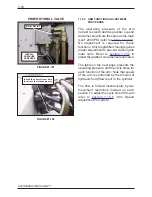
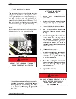
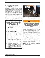
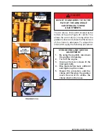
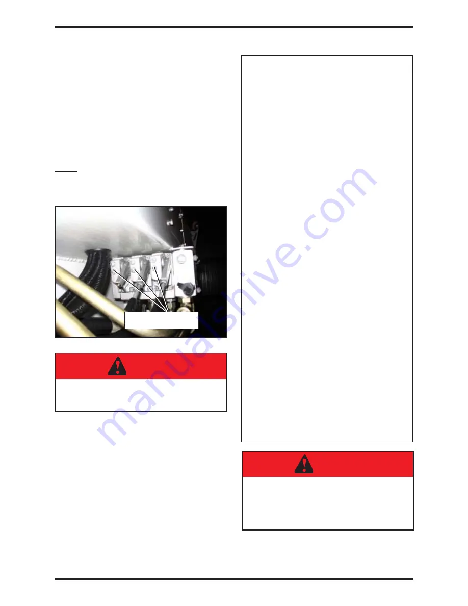
restrictor or stopper (Figure #1.107).
Note:
No arm speed adjustment is required unless
replacing the valve or a section of it.
SPEED ADJUSTMENT
PROCEDURE
1.
Apply the lockout/tagout
procedure.
2.
Secure the arm’s working area
using barrier tape or barricades.
3.
Put the transmission to neutral.
4.
Start the engine and engage the
hydraulic system (Pump switch
“ON”).
5.
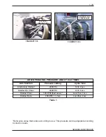
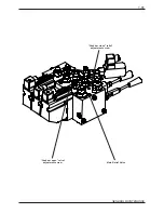
Clearly identify the stopper screw
on the valve that corresponds to
the proper function (boom
extension/retraction, grabber
open/close). Move the lever to
evaluate the speed of the arm then
release the lever.
6.
Loosen the lock nut.
7.
Screw in the restrictor adjustment
only one eighth (1/8th) of a turn at
a time to see a significant change
of the arm’s speed.
8.
Move the lever again to evaluate
the arm’s speed. Repeat until cycle
times are properly set (see cycle
time on page 7).
9.
Tighten the lock nut.
*
Limiting the stroke of the spools is
limiting the amount of oil (flow) going
through them. Controlling the flow
of oil means controlling the speed of
the arm.
DO NOT STAND DIRECTLY IN THE
PATH OF THE ARM WHILE
CARRYING OUT THESE
ADJUSTMENTS.
APPLY THE “LOCKOUT/TAGOUT”
PROCEDURE AT ALL TIMES.
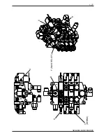
FIGURE #1.107
MOVEMENT
RESTRICTORS
Summary of Contents for Automizer Versa Hand
Page 2: ...AUTOMIZER VERSA HANDTM 1 2...
Page 4: ...AUTOMIZER VERSA HANDTM 1 4...
Page 8: ...AUTOMIZER VERSA HANDTM 1 8...
Page 58: ...AUTOMIZER VERSA HANDTM 1 58 FIGURE 1 81 INPUT OUTPUT COVER ELECTRICAL COILS...
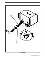
Page 69: ...1 69 GENERAL MAINTENANCE FIGURE 1 89A Strainer Seal...
Page 77: ...1 77 GENERAL MAINTENANCE A B C BEHIN D D F MAIN RELIEF B E...
Page 105: ...1 105 GENERAL MAINTENANCE NOTES...


