AUTOMIZER
VERSA HAND
TM
1-90
1.17.2
GRABBER AND ARM LIMIT
SWITCHES
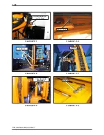
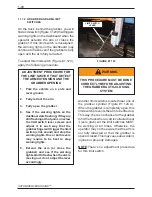
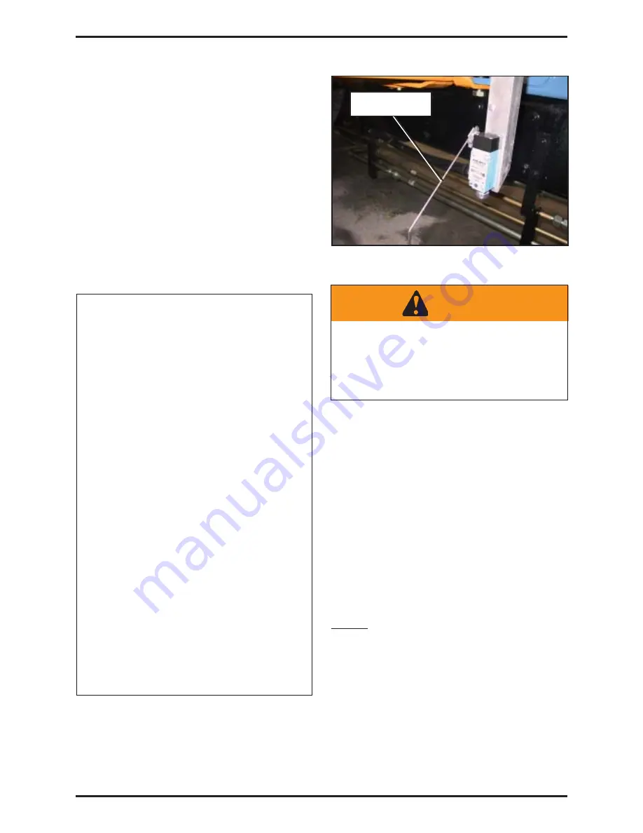
On the truck, behind the grabber, you will
find a limit switch (Figure 1.123) that triggers
warning lights on the dashboard when the
operator extends the arm or closes the
grabber. If this limit switch is misaligned,
the warning lights on the dashboard may
continue to flash even if the grabber is fully
open and the arm fully retracted.
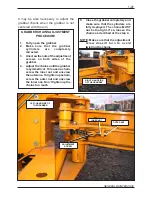
To adjust this limit switch (Figure # 1.123),
apply the following procedure:
ADJUSTMENT PROCEDURE FOR
THE LIMIT SWITCH THAT DETECT
THE ARM EXTENSION AND THE
GRABBER OPENING
1.
Park the vehicle on a safe and
level ground.
2.
Fully retract the arm.
3.
Fully open the grabber.
4.
See if the warning lights on the
dashboard are flashing; if they are
still flashing at that point, unscrew
the limit switch lever screws and
adjust it in such way that the
grabber finger will trigger the limit
switch (click sound) and stop the
warning lights. One or both levers
may require to be bent to stop
warning lights.
5.
Extend the arm (or close the
grabber) and see if the warning
lights start to flash when the arm is
moving out. If not, adjust the lever
accordingly.
FIGURE #1.123
LIMIT SWITCH
LEVER
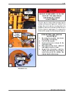
Another limit switch is located near one of
the grabber cylinder (Figure #1.124 A).
When the grabber is completely open, this
limit switch prevents the arm to be lifted up.
This way, there’s no chance for the grabber
to hit the truck when a cart is collected near
it (zero grab). All the limit switches MUST
be working at all times. Otherwise, the
operator may not be aware that the arm is
not fully retracted or that the grabber is
open or closed. This may cause an accident,
injuries or property damages.
NOTE:There’s no adjustment procedure
for this limit switch.
WARNING
THIS PROCEDURE MUST BE DONE
CORRECTLY BEFORE ADJUSTING
THE GRABBER AUTO-CLOSING
SYSTEM
Summary of Contents for Automizer Versa Hand
Page 2: ...AUTOMIZER VERSA HANDTM 1 2...
Page 4: ...AUTOMIZER VERSA HANDTM 1 4...
Page 8: ...AUTOMIZER VERSA HANDTM 1 8...
Page 58: ...AUTOMIZER VERSA HANDTM 1 58 FIGURE 1 81 INPUT OUTPUT COVER ELECTRICAL COILS...
Page 69: ...1 69 GENERAL MAINTENANCE FIGURE 1 89A Strainer Seal...
Page 77: ...1 77 GENERAL MAINTENANCE A B C BEHIN D D F MAIN RELIEF B E...
Page 105: ...1 105 GENERAL MAINTENANCE NOTES...

