1-91
GENERAL MAINTENANCE
DANGER
DO NOT STAND DIRECTLY IN THE
PATH OF THE ARM WHILE
CARRYING OUT THESE
ADJUSTMENTS.
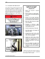
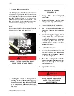
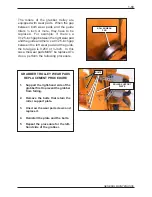
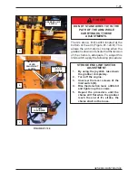
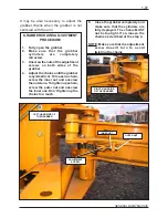
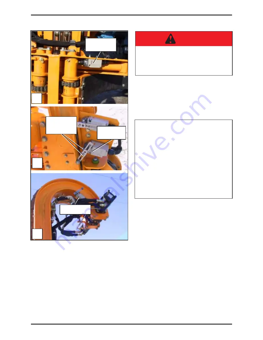
There’s also a limit switch located at the
bottom of the arm (Figure #1.124 B). This
allows the arm motor(s) to stop when the
grabber is down and ensure that the tension
of the chains is adequate. To adjust this
limit switch, apply the following procedure:
CLIMB
CUSHIONING
FIGURE #1.124
GRABBER LIMIT
SWITCH
LIMIT SWITCH
(END OF
STROKE)
STROKE END LIMIT SWITCH
ADJUSTMENT
1.
By using the joystick, take down
the grabber completely.
2.
Turn off the engine.
3.
Unscrew the lever screws of the
limit switch (B).
4.
Rise the detection lever a little bit
and tighten up the screws.
5.
Repeat the procedure until the
chains still flat when the grabber
reach the end of it’s stroke. the
chains shall not be loose.
A
B
C
DETECTION
LEVER
ADJUSTMENT
SCREWS
Summary of Contents for Automizer Versa Hand
Page 2: ...AUTOMIZER VERSA HANDTM 1 2...
Page 4: ...AUTOMIZER VERSA HANDTM 1 4...
Page 8: ...AUTOMIZER VERSA HANDTM 1 8...
Page 58: ...AUTOMIZER VERSA HANDTM 1 58 FIGURE 1 81 INPUT OUTPUT COVER ELECTRICAL COILS...
Page 69: ...1 69 GENERAL MAINTENANCE FIGURE 1 89A Strainer Seal...
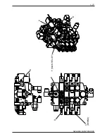
Page 77: ...1 77 GENERAL MAINTENANCE A B C BEHIN D D F MAIN RELIEF B E...
Page 105: ...1 105 GENERAL MAINTENANCE NOTES...

